VN01 016 0015 1 Amphenol, VN01 016 0015 1 Datasheet - Page 22
VN01 016 0015 1
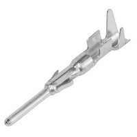
Manufacturer Part Number
VN01 016 0015 1
Description
Heavy Duty Power Connectors STAMPED MALE CONTACT 20-16 AWG HI CURRENT
Manufacturer
Amphenol
Series
C146 Seriesr
Datasheet
1.TA_0500.pdf
(32 pages)
Specifications of VN01 016 0015 1
Contact Material
Brass
Contact Plating
Silver
Insert / Contact Gender
Male
Number Of Positions / Contacts
1
Product Type
Contacts
Termination Style
Crimp
Wire Gauge Range
20-16
Lead Free Status / RoHS Status
Lead free / RoHS Compliant


22
Abisolierung der Leitung
Das Abisolieren der Leitung hat mit der nötigen Sorgfalt zu geschehen, um
Fehler auszuschließen. Die Leiterabisolierlänge ist so zu wählen, dass im
gecrimpten Zustand
- zwischen Leitercrimp und Isolierungshalterung der Leiter und dessen
- das Ende des gecrimpten Leiters aus dem vorderen Crimphülsenende
Crimpverbindungen
Für eine einwandfreie Crimpverbindung, die alle an sie gestellten
elektrischen und mechanischen Anforderungen erfüllt, sind folgende
Einzelheiten aufeinander abgestimmt:
- Zuordnung der verarbeitbaren Leiterquerschnitte zur Crimphöhe
- Crimphülsenform (Blechdicke, Länge usw.)
- Crimpprofile (Crimpbreite)
- Leitercrimphöhe
- Ausformung der Isolierungshalterung
Verarbeitung von Crimpkontakten
Bei der Verarbeitung von Crimpkontakten sind die Herstellerhinweise zu
beachten. Sie enthalten in der Regel folgende Informationen:
- Handhabungshinweise
- Zuordnung von Kontakten zum Crimpprofil des Handcrimpwerkzeuges
- Zuordnung von Kontakten in Bandform zum Werkzeug der Crimpmaschine
- Leiterquerschnittsbereich des Kontaktes
- Durchmesserbereich der Leiterisolierung
- Zuordnung von Kontakten in Bandform zum Werkzeug der Crimpmaschine
Die folgende Bildserie zeigt den Ablauf des Crimpvorganges bei einer
offenen Crimphüllse
Technische
Informationen
zur Crimptechnik
Technical
information on
crimp technology
Isolierhülle sichtbar sind,
herausragt. Der Steck- und Anschlussbereich darf nicht beeinträchtigt
werden.
(bei mehreren Crimpprofilen)
Abisolierter Leiter, in oder über
der Leitercrimphülse positioniert
Stripped wire in or above the
conductor crimp barrel
Offene Crimphülse mit
geschrägten Außenflanken
Open crimp barrel with chambered
outer flanks
Die geschrägten Außenflanken dienen
der besseren Führung der Crimphülse
in der Obermatrize als auch dem besseren
Einrollen der Crimphülsen flanken
Better guidance of the crimp barrel in the crimp
indentor by the chambered outer flanks
Untermatrize (Amboss)
Crimp anvil
Obermatrize und die sich einrollenden
Crimphülsenflanken zwingen das
ab isolierte Leiterende in den Crimp-
hülsenboden
The indentor and the rolling up crimp flanks
force the stripped conductor end into the base
of the crimp barrel
Obermatritze (Crimpstempel)
Crimp indentor
Stripping of the wire
Attention should be paid to the stripping of the wire, to avoid faults. The
stripping length shall be chosen to the following conditions:
- the conductor (strands) should be visible between crimp barrel and
- the end of the crimped conductor should protrude out of the anterior end of
Crimp connections
In order to achieve a good reliable crimped connection and to meet all
electrical and mechanical requirements the following details are harmonized:
- assignment of processible conductor cross-sections to crimping height
- shape of the crimp barrel (thickness, length etc.)
- crimping-profile (crimping width)
- crimping height
- forming to shape of insulation grip
Processing of crimp contacts
During the processing of crimp contacts, attention should be paid to
manufacturer’s instructions. They should include the following information:
- Handling information
- Allocation of contacts to the crimp profile of the hand-operated crimping
- Allocation of bandoliered contacts to the tool of the crimping machine
- Conductor cross section
- Diameter of insulation
- Allocation of contacts to the tool of the crimping machine
The following figures show the crimping process of an open crimp barrel
insulation grip,
the crimp barrel. Mating and termination area should not be damaged.
tool (with several profiles)
Die beiden eingerollten Crimp-
hülsen flanken treffen sich in der
Obermatrize und werden nach
innen gepresst
Both rolled crimp barrel flanks meet
each other within the crimp indentor
and will be pressed further
Die vorgegebene Crimphöhe ist
erreicht, das Crimpwerkzeug
öffnet sich und die Crimpver-
bindung ist fertig
The specified crimping height has been
reached, the crimping tool opens and
the crimp connection is complete
Related parts for VN01 016 0015 1
Image
Part Number
Description
Manufacturer
Datasheet
Request
R

Part Number:
Description:
Circular DIN Connectors PIN CONTACT
Manufacturer:
Amphenol

Part Number:
Description:
Heavy Duty Power Connectors PIN CONTACT
Manufacturer:
Amphenol
Part Number:
Description:
Heavy Duty Power Connectors PIN CONTACT
Manufacturer:
Amphenol
Part Number:
Description:
Heavy Duty Power Connectors PIN CONTACT
Manufacturer:
Amphenol
Part Number:
Description:
Heavy Duty Power Connectors PIN CONTACT
Manufacturer:
Amphenol
Part Number:
Description:
Cable Specification: PU CABLE, UL20549 24AWG*8C+AD,OD= 6.0mm
Manufacturer:
Amphenol