C146 10G003 500 4 Amphenol, C146 10G003 500 4 Datasheet - Page 190
C146 10G003 500 4
Manufacturer Part Number
C146 10G003 500 4
Description
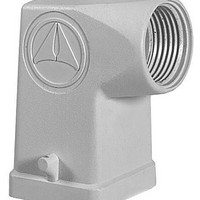
Heavy Duty Power Connectors SIDE ENTRY HOOD FOR 7 CONT INSERT PG11
Manufacturer
Amphenol
Series
C146 Seriesr
Datasheet
1.C146_10F003_000_4.pdf
(212 pages)
Specifications of C146 10G003 500 4
Housing Material
Aluminum, Diecast Alloy
Hood Orientation
Side
Number Of Positions / Contacts
3
Product Type
Housings
Termination Style
Screw
Lead Free Status / RoHS Status
Lead free / RoHS Compliant


190
C 146
Technische Informationen
Technical information
Tabelle 10
Bei der Festlegung der Mindestluftstrecken von Steckverbindern sind in
der Regel die Werte des inhomogenen Falls anzuwenden bzw. ist die
entsprechende Luftstrecke durch eine Spannungsprüfung zu überprüfen.
Kriechstrecken
Die Kriechstrecke ist die kürzeste Entfernung entlang der Oberfläche
eines Isolierstoffes zwischen zwei leitenden Teilen.
Zur Bemessung der Kriechstrecke wird die aus der entsprechenden
Netzart abgeleitete Bemessungsspannung und die bereits bei der
Luftstrecke gewählte Zuordung des Verschmutzungsgrades
herangezogen. Außerdem wird die Kriechwegbildung des vom Hersteller
verwendeten Isolierstoffes berücksichtigt. Die Isolierstoffe werden
entsprechend ihrem Kriechwegbildungsfaktor CTI (Comparative Tracking
Index) in vier Gruppen eingeteilt:
Isolierstoffgruppe I
Isolierstoffgruppe II
Isolierstoffgruppe IIIa 175 ≤ CTI <400
Isolierstoffgruppe IIIb 100 ≤ CTI <175
Bemessungs-
Stoßspannung
in kV
Impulse
withstand
voltage
in kV
0,33
0,40
0,50
0,60
0,80
1,0
1,2
1,5
2,0
2,5
3,0
4,0
5,0
6,0
8,0
10
12
15
20
25
30
40
50
60
80
100
Mindestluftstrecken in mm bis zu 2000 m über NN
Minimum clearances in air in mm up to 2000 m above sea level
Fall A (inhomogenes Feld)
Case A (non homogeneous field)
Verschmutzungsgrad
Pollution degree
1
0,01
0,02
0,04
0,06
0,10
0,15
0,25
0,5
1,0
1,5
2
3
4
5,5
8
11
14
18
25
33
40
60
75
90
130
170
600 ≤ CTI
400 ≤ CTI <600
2
0,2
0,25
0,5
1,0
1,5
2
3
4
5,5
8
11
14
18
25
33
40
60
75
90
130
170
3
0,8
1,0
1,5
2
3
4
5,5
8
11
14
18
25
33
40
60
75
90
130
170
4
1,6
2
3
4
5,5
8
11
14
18
25
33
40
60
75
90
130
170
Chart 10
When defining the minimum clearances for connectors generally the
values of the inhomogeneous field can be chosen or the required
clearance has to be defined by a voltage test.
Creepage distances
The creepage distance is the shortest distance along the surface of the
insulating material between two conductive parts.
For the dimensioning of the creepage distance the following factors are
taken into account: the rated voltage, the pollution degree and the
tracking formation of the insulating material. The materials are
separated into four groups according to their CTI values (Comparative
Tracking Index):
Material group I
Material group II
Material group IIIa
Material group IIIb
Fall B (homogenes Feld)
Case B (homogeneous field)
Verschmutzungsgrad
Pollution degree
1
0,01
0,02
0,04
0,06
0,1
0,15
0,2
0,3
0,45
0,6
0,8
1,2
1,5
2
3
3,5
4,5
5,5
8
10
12,5
17
22
27
35
45
2
0,2
0,3
0,45
0,6
0,8
1,2
1,5
2
3
3,5
4,5
5,5
8
10
12,5
17
22
27
35
45
600 ≤ CTI
400 ≤ CTI < 600
175 ≤ CTI < 400
100 ≤ CTI < 175
3
0,8
1,2
1,5
2
3
3,5
4,5
5,5
8
10
12,5
17
22
27
35
45
4
1,6
2
3
3,5
4,5
5,5
8
10
12,5
17
22
27
35
45
Amphenol
Related parts for C146 10G003 500 4
Image
Part Number
Description
Manufacturer
Datasheet
Request
R

Part Number:
Description:
Heavy Duty Power Connectors PIN MODUL 10 WAY
Manufacturer:
Amphenol

Part Number:
Description:
Heavy Duty Power Connectors SOCKET MODULE 10 WAY
Manufacturer:
Amphenol

Part Number:
Description:
Heavy Duty Power Connectors PIN CONNECTOR 10 WAY
Manufacturer:
Amphenol

Part Number:
Description:
Heavy Duty Power Connectors FEMALE CONNECTOR 10 WAY
Manufacturer:
Amphenol

Part Number:
Description:
Cable Specification: PU CABLE, UL20549 24AWG*8C+AD,OD= 6.0mm
Manufacturer:
Amphenol