0933-0-15-20-75-14-11-0 Mill-Max Manufacturing Corp., 0933-0-15-20-75-14-11-0 Datasheet
0933-0-15-20-75-14-11-0
Manufacturer Part Number
0933-0-15-20-75-14-11-0
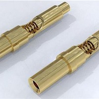
Description
Headers & Wire Housings
Manufacturer
Mill-Max Manufacturing Corp.
Series
0933 Seriesr
Datasheets
1.0950-0-15-20-71-14-11-0.pdf
(1 pages)
2.0950-0-15-20-71-14-11-0.pdf
(1 pages)
3.0933-0-15-20-75-14-11-0.pdf
(2 pages)
Specifications of 0933-0-15-20-75-14-11-0
Product Type
Contacts
Contact Gender
Pin (Male)
Number Of Positions / Contacts
1
Mounting Style
Through Hole
Mounting Angle
Vertical
Termination Style
Solder Cup
Featured Product
0962/0933 Spring Pins
Plating
Gold
Plating - Thickness
20µin (0.51µm)
Mounting Type
Through Hole
Lead Free Status / RoHS Status
Lead free / RoHS Compliant
w w w. m i l l - m a x . c o m
Solder Mount in 0,46 min. mounting hole
0950
0916
0950-0-15-20-71-14-11-0
0,48 DIA.
0,48 DIA.
0,94 DIA.
0,94 DIA.
1,07 DIA.
1,07 DIA.
1,09 DIA.
1,09 DIA.
0,41 DIA.
0,41 DIA.
ORDER CODE: 09XX - X - 15 - 20 - 7X - 14 - 11 - 0
TOLERANCES ON: LENGTHS:
SLEEVE & PLUNGER MATERIAL: Copper Alloy
SPRING MATERIAL:
SLEEVE & PLUNGER FINISH: 0,51 μm Gold over Nickel
SPRING FINISH: 0,25 μm Gold over Nickel
DIMENSION IN INCHES:
0916-0-15-20-77-14-11-0
P.C.B. PAD
P.C.B. PAD
2,03
2,03
2,29
2,29
Horizontal Surface mount
Standard Stroke
5,26
5,26
7,54
7,54
Long Stroke
0,64
0,64
0,7
0,7
STROKE
STROKE
MATERIAL SPECIFICATIONS:
0,71
0,71
MID
MID
DIAMETERS: ±0,05
ANGLES:
Beryllium Copper
Spring Number
1,4
1,4
STROKE
STROKE
MAX
MAX
2,62
2,62
4,7
4,7
STROKE
STROKE
2,29
2,29
1,14
1,14
MID
MID
8,92
8,92
STROKE
STROKE
MAX.
MAX.
1,88
1,88
1,7
1,7
±0,15
± 2°
0951
0951-0-15-20-71-14-11-0
0,48 DIA.
0,48 DIA.
0,94 DIA.
0,94 DIA.
1,07 DIA.
1,07 DIA.
1,09 DIA.
1,09 DIA.
0,76 DIA.
0,76 DIA.
Standard Stroke, Surface mount
Discrete Spring-Loaded Contacts
SPRING-LOADED CONNECTORS
High profile
P.C.B. Layout
0,7
0,7
0,25
0,25
2,29
2,29
STROKE
STROKE
0,64
0,64
MID
MID
2002/95/EC
RoHS
1,4
1,4
0,71
0,71
STROKE
STROKE
4,72
4,72
1,96
1,96
MAX
MAX
6,4
6,4
17.1
0933
NUMBER
0933-0-15-20-75-14-11-0
SPRING
1,07 DIA.
1,07 DIA.
1,5 DIA.
1,5 DIA.
1,63 DIA.
1,63 DIA.
1,83 DIA.
1,83 DIA.
1,98 DIA.
1,98 DIA.
1,65 DIA.
1,65 DIA.
0,89 DIA.
0,89 DIA.
HOLE
HOLE
71
75
77
Standard Stroke, SolderCup
For Wire Termination
MECHANICAL & ELECTRICAL SPECIFICATIONS:
CURRENT RATING: 2A continuous, 3A peak
STROKE
0,64
0,64
0,7
0,7
CONTACT RESISTANCE: 20 mΩ max.
Springs are not Interchangeable
Mid.
1,14
0,7
0,7
STROKE
STROKE
2,26
2,26
MID
MID
0,71
0,71
DURABILITY: 1,000,000 cycles
4,57
4,57
1,4
1,4
STROKE
STROKE
6,43
6,43
3,38
3,38
MAX
MAX
11,2
11,2
STROKE
Max.
2,29
1,4
1,4
0962
0962-0-15-20-75-14-11-0
1,07 DIA.
1,07 DIA.
1,5 DIA.
1,5 DIA.
1,63 DIA.
1,63 DIA.
1,83 DIA.
1,83 DIA.
1,98 DIA.
1,98 DIA.
1,65 DIA.
1,65 DIA.
0,89 DIA.
0,89 DIA.
HOLE
HOLE
Standard Stroke, Crimp Barrel
5 1 6 - 9 2 2 - 6 0 0 0
For Wire Termination
Mid. Stroke
FORCE @
50 g
60 g
60 g
0,64
0,64
0,7
0,7
STROKE
STROKE
MID
MID
1,17
1,17
Initial Force
3,18
3,18
(Pre-load)
0,71
0,71
1,4
1,4
15 g
25 g
25 g
STROKE
STROKE
MAX
MAX
6,43
6,43
3,38
3,38
PINS
11,2
11,2
Related parts for 0933-0-15-20-75-14-11-0
Image
Part Number
Description
Manufacturer
Datasheet
Request
R

Part Number:
Description:
MILLMAX PART
Manufacturer:
Mill-Max Manufacturing Corp.

Part Number:
Description:
CONN SPRING LOADED PIN .177 GOLD
Manufacturer:
Mill-Max Manufacturing Corp.
Datasheet:

Part Number:
Description:
CONN SPRING LOADED PIN .197 GOLD
Manufacturer:
Mill-Max Manufacturing Corp.
Datasheet:

Part Number:
Description:
CONN SPRING LOADED PIN .236 GOLD
Manufacturer:
Mill-Max Manufacturing Corp.
Datasheet:

Part Number:
Description:
CONN SPRING LOADED PIN .217 GOLD
Manufacturer:
Mill-Max Manufacturing Corp.
Datasheet: