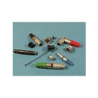
JBXER1G06FCSDSR Souriau Connection Technology, JBXER1G06FCSDSR Datasheet - Page 3

JBXER1G06FCSDSR
Manufacturer Part Number
JBXER1G06FCSDSR
Description
Circular Push Pull Connectors RCP SHELL 1 P6 CRMP WIRE SIZE 26-22
Manufacturer
Souriau Connection Technology
Series
JBXr
Datasheet
1.JBX2OUTLP09.pdf
(4 pages)
Specifications of JBXER1G06FCSDSR
Product Type
Connectors
Shell Style
Receptacle
Number Of Contacts
6
Shell Size
1
Termination Style
Crimp
Lead Free Status / RoHS Status
Lead free / RoHS Compliant
Contacts layouts
Note : Contact numbering mating faces receptacle view: counterclockwise from key at position 1
**Inserts with fixed non removable contacts
Male Insulator Wire Side
Male Insulator Wire Side
Male Insulator Wire Side
Solder
Crimp
PCB Straight Tails
PCB Right Angle*
Contact Diameter mm
Solder
Crimp
PCB Straight Tails*
PCB Right Angle*
Contact Diameter mm
Solder
Crimp
PCB Straight Tails*
PCB Right Angle*
Contact Diameter mm
Contact numbering mating faces plug view: clockwise from key at position 1
Shell size 00
Shell size 1
Shell size 0
Push Pull Connectors
04
S
0.5
02
S
C
1.3
02
S
C
P
Q
0.9
P
03
1.3
S
C
P
Q
03
* For receptacles with female contacts.
0.9
• Voltage Test Procedure
-
- The working voltage corresponds to the maximum voltage the connector is able to withstand
• Maximum current rating
- This indicated maximum current rating corresponds to the maximum current that can be ap-
Remark : If the current is applied on only one contact of the layout, then an increased current
value can be achieved over a long duration.
S
C
P
Q
The testing voltage corresponds to the maximum voltage the connector is able to withstand
in normal climatic conditions. The value is about 75% of the electrical breakdown voltage. The
testing voltage level can be reached several times in connectors life, but never applied for a con-
tinuous duration.
continuously during its life time, in real environmental conditions, even with high temperature.
The value is around 1/3 of the testing voltage
plied simultaneously on each line of the connector mated pair, continuously during its life
time, in normal climatic conditions.
0.9
S
C
P
Q
04
04
0.7
S**
C
P
Q
0.9
05
S
C
P
Q
05
Q
0.7
S**
C
P
S**
C
0.7
P
06
Q
0.5
06
P
S**
S**
C
0.7
07
P
.
Q
S**
0.7
07
S**
08
P
Q
C
P
0.5
0.5
S**
P
0.5
S**
10
P
08
12
S**
0.5
P
Options
• Protective boot
With each JBX connector, one protective
boot can accept diverse cable diameters
thus the end-user can manage various
cable diameters without bothering with
multiple part numbers.
• Caps : an efficient protection
against dust
KEYING
Keying angle
Receptacle
Plug
Push Pull Connectors
Part number
JBX BR3
JBX BR2
JBX BR0
JBX BR1
Receptacle Caps
JBX 00 MPN
0°
JBX 0 MP*
JBX 1 MP*
JBX 2 MP*
JBX 3 MP*
Color code
number
Part
A
B
G
J
M
N
R
V
O
* Color code - See chart below / In size 00, available only in black
Shell
Size
0
1
2
3
45°
Shell
size
00
0
1
3
2
Part number
Colors
blue
white
grey
yellow
brown
black
red
green
orange
JBX BF0
JBX BF1
JBX BF2
JBX BF3
JBX BF00
Plug Caps
Ø A
1.5
2.2
2.6
4
5
37.5°
Parts that require a protective boot
need to be ordered with an M
suffix. Protective boots are ordered
separately.
Dual Key Way
Material : ELASTOLLAN (PUR)
Working temperature :
- 40°C ; + 80°C
- 40°F ; + 176°F
Shell
Size
00
1
0
2
15
3
20
25
30
35
L
Dimensions
30°
1.5
3.5
4.9
min
1
2
Ø Cable
60°
max
3.5
5.5
7.5
9.7
12


