CPF1100R00FKE14 Vishay, CPF1100R00FKE14 Datasheet - Page 2
CPF1100R00FKE14
Manufacturer Part Number
CPF1100R00FKE14
Description
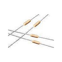
Metal Film Resistors - Through Hole 1watt 100ohms 1% 100ppm
Manufacturer
Vishay
Series
CPFr
Type
Metal Film Resistors Industrial Power Flameproofr
Datasheet
1.CPF212K000FKE14.pdf
(3 pages)
Specifications of CPF1100R00FKE14
Resistance
100 Ohms
Power Rating
1 Watt
Voltage Rating
250 Volts
Temperature Coefficient
+/- 100 PPM / C
Tolerance
1 %
Termination Style
Axial
Operating Temperature Range
- 65 C to + 230 C
Dimensions
2.29 mm Dia. x 6.1 mm L
Resistance Tolerance
± 1%
Resistor Element Material
Metal Film
Lead Free Status / RoHS Status
Lead free / RoHS Compliant
Lead Free Status / RoHS Status
Lead free / RoHS Compliant, Lead free / RoHS Compliant
Other names
CPF1100R00FKE


DIMENSIONS
Notes
(1)
• Surface temperatures were taken with an infrared pyrometer in
Document Number: 31021
Revision: 11-Mar-10
THERMAL RESISTANCE
MATERIAL SPECIFICATIONS
Element
Core
Coating
Termination
PERFORMANCE
TEST
Thermal Shock
Short Time Overload
Low Temperature Operation
Moisture Resistance
Resistance To Soldering Heat
Shock
Vibration
Terminal Strength
Dielectric Withstanding Voltage
Life
1.08 ± 0.125 (27.43 ± 3.18) if tape and reel
+ 25 °C still air. Resistors were supported by their leads in test
clips at a point 0.500" (12.70 mm) out from the resistor body ends.
250
200
150
100
50
0
0
1.50 ± 0.125
[38.10 ± 3.18]
1
(1)
Special high temperature conformal coat
Metal Film Resistors, Industrial Power, Precision, Flameproof
Standard lead material is solder-coated
Proprietary nickel-chrome alloy
CPF1
L
Solderable and weldable per
Cleaned high purity ceramic
1 max.
L
2
MIL-STD-1276, Type C
For technical questions, contact:
CPF2
D
3
APPLIED POWER IN W
d
CPF3
4
5
DERATING
ff2aresistors@vishay.com
GLOBAL
MODEL
CPF1
CPF2
CPF3
MECHANICAL SPECIFICATIONS
Terminal Strength
Solderability
120
100
80
60
40
20
- 55
0
- 25
0.240 ± 0.020
0.344 ± 0.031
0.555 ± 0.041
(14.10 ± 1.04)
(6.10 ± 0.51)
(8.74 ± 0.79)
MAX. ΔR (Typical Test Lots)
0
L
DIMENSIONS in inches (millimeters)
30
± 1.0 %
± 0.5 %
± 0.5 %
± 1.5 %
± 0.5 %
± 0.5 %
± 0.5 %
± 0.5 %
± 0.5 %
± 2.0 %
(4.57 ± 0.381)
0.090 ± 0.008
0.145 ± 0.015
0.180 ± 0.015
60
(2.29 ± 0.20)
(3.68 ± 0.38)
70
Continuous satisfactory coverage
when tested in accordance with
D
90 120
MIL-STD-202, Method 208
2 pound pull test
(10.80)
(16.51)
L
(7.87)
0.310
0.425
0.650
AMBIENT TEMP. IN °C
150 180
1 max.
Vishay Dale
www.vishay.com
0.025 ± 0.002
0.032 ± 0.002
0.032 ± 0.002
(0.64 ± 0.05)
(0.81 ± 0.05)
(0.81 ± 0.05)
210
CPF
d
240
99
Related parts for CPF1100R00FKE14
Image
Part Number
Description
Manufacturer
Datasheet
Request
R

Part Number:
Description:
357-036-542-201 CARDEDGE 36POS DL .156 BLK LOPRO
Manufacturer:
Vishay
Datasheet:
Part Number:
Description:
357-036-542-201 CARDEDGE 36POS DL .156 BLK LOPRO
Manufacturer:
Vishay
Datasheet:
Part Number:
Description:
357-036-542-201 CARDEDGE 36POS DL .156 BLK LOPRO
Manufacturer:
Vishay
Datasheet:
Part Number:
Description:
357-036-542-201 CARDEDGE 36POS DL .156 BLK LOPRO
Manufacturer:
Vishay
Datasheet:
Part Number:
Description:
357-036-542-201 CARDEDGE 36POS DL .156 BLK LOPRO
Manufacturer:
Vishay
Datasheet:
Part Number:
Description:
357-036-542-201 CARDEDGE 36POS DL .156 BLK LOPRO
Manufacturer:
Vishay
Datasheet:
Part Number:
Description:
357-036-542-201 CARDEDGE 36POS DL .156 BLK LOPRO
Manufacturer:
Vishay
Datasheet:
Part Number:
Description:
357-036-542-201 CARDEDGE 36POS DL .156 BLK LOPRO
Manufacturer:
Vishay
Datasheet:
Part Number:
Description:
357-036-542-201 CARDEDGE 36POS DL .156 BLK LOPRO
Manufacturer:
Vishay
Datasheet:
Part Number:
Description:
357-036-542-201 CARDEDGE 36POS DL .156 BLK LOPRO
Manufacturer:
Vishay
Datasheet:
Part Number:
Description:
357-036-542-201 CARDEDGE 36POS DL .156 BLK LOPRO
Manufacturer:
Vishay
Datasheet:
Part Number:
Description:
357-036-542-201 CARDEDGE 36POS DL .156 BLK LOPRO
Manufacturer:
Vishay
Datasheet:
Part Number:
Description:
357-036-542-201 CARDEDGE 36POS DL .156 BLK LOPRO
Manufacturer:
Vishay
Datasheet:
Part Number:
Description:
357-036-542-201 CARDEDGE 36POS DL .156 BLK LOPRO
Manufacturer:
Vishay
Datasheet:
Part Number:
Description:
357-036-542-201 CARDEDGE 36POS DL .156 BLK LOPRO
Manufacturer:
Vishay
Datasheet: