B82131A5402M EPCOS Inc, B82131A5402M Datasheet
B82131A5402M
Specifications of B82131A5402M
Available stocks


Related parts for B82131A5402M


B82131A5402M Summary of contents
Page 1
Inductors VHF chokes Series/Type: B82131, B82132, B82133, B82134 Date: March 2008 Data Sheet Data Sheet EPCOS AG 2008. Reproduction, publication and dissemination of this publication, enclosures hereto and the information contained therein without EPCOS’ prior express consent is prohibited. ...
Page 2
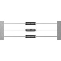
VHF chokes Rated voltage 500 V AC/DC Rated current 0. Rated inductance 1 µH to 420 µH Construction ■ Cylinder core of carbonyl iron ■ Winding: single-layer, enamel copper wire ■ Polyester insulating sleeve Features ■ ...
Page 3
VHF chokes Dimensional drawing max. k max. *) Tolerance over 10 spacings ±2 mm Dimensions in mm Reel packing 30 95+1 107 max. Dimensions in mm Please read Cautions and warnings and Important notes at the ...
Page 4
VHF chokes Technical data and measuring conditions Test voltage V test Rated inductance L R Inductance tolerance Rated temperature T R Rated current resistance R typ Resonance frequency f res Solderability (lead-free) Resistance to soldering heat (wave ...
Page 5
... B82133A5401M000 2.8 B82134A5401M000 0.8 B82131A5701M000 1.0 B82132A5701M000 2.4 B82133A5701M000 3.0 B82134A5701M000 0.8 B82131A5152M000 1.1 B82132A5152M000 2.5 B82133A5152M000 3.2 B82134A5152M000 0.8 B82131A5202M000 1.1 B82132A5202M000 2.8 B82133A5202M000 3.3 B82134A5202M000 1.0 B82131A5302M000 1.2 B82132A5302M000 2.9 B82133A5302M000 3.5 B82134A5302M000 1.1 B82131A5402M000 1.4 B82132A5402M000 3.0 B82133A5402M000 ...
Page 6
VHF chokes Impedance |Z| versus frequency f measured with impedance analyzer Agilent 4294A or S-parameter network analyzer Agilent 8753ES, typical values at 20 °C B82131A5***M000 6 10 B82131 Ω A5151 A5301 A5401 ...
Page 7
VHF chokes Current derating versus ambient temperature T (rated temperature ° 1.0 0.8 0.6 0.4 0 100 A IND0143-T-E ˚ C ...
Page 8
Cautions and warnings ■ Please note the recommendations in our Inductors data book (latest edition) and in the data sheets. – Particular attention should be paid to the derating curves given there. – The soldering conditions should also be observed. ...
Page 9
Important notes The following applies to all products named in this publication: 1. Some parts of this publication contain statements about the suitability of our products for certain areas of application. These statements are based on our knowledge of typical ...