RLF7030T6R8M2R8 TDK Corporation, RLF7030T6R8M2R8 Datasheet - Page 2
RLF7030T6R8M2R8
Manufacturer Part Number
RLF7030T6R8M2R8
Description
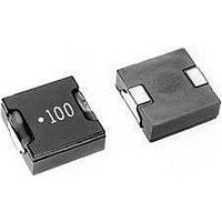
Power Inductors 6.8uH 2.8A
Manufacturer
TDK Corporation
Series
RFLr
Datasheet
1.RLF7030T-4R7M3R4.pdf
(2 pages)
Specifications of RLF7030T6R8M2R8
Product
Power Inductor
Test Frequency
100 KHz
Inductance
6.8 uH
Tolerance
20 %
Maximum Dc Current
2.8 Amps
Maximum Dc Resistance
45 mOhms
Dimensions
6.8 mm W x 7.3 mm L x 3.2 mm H
Operating Temperature Range
- 40 C to + 85 C
Termination Style
SMD/SMT
Lead Free Status / RoHS Status
Lead free / RoHS Compliant


SHAPES AND DIMENSIONS/RECOMMENDED PC BOARD PATTERN
ELECTRICAL CHARACTERISTICS
Inductance
(µH)
1
1.5
2.2
3.3
4.7
6.8
∗
TYPICAL ELECTRICAL CHARCTERISTICS
INDUCTANCE CHANGE vs. DC SUPERPOSITION
CHARACTERISTICS
• All specifications are subject to change without notice.
Rated current: Value obtained when current flows and the temperature has risen to 40°C or when DC current flows and the nominal value of inductance
has fallen by 30%, whichever is smaller.
Winding start mark
7
6
5
4
3
2
1
0
0
7.3max.
1
6.8µH
4.7µH
3.3µH
2.2µH
1.5µH
1.0µH
2
Inductance
tolerance
±30%
±30%
±20%
±20%
±20%
±20%
3
DC current ( A )
4
Terminal
electrode
3.2max.
5
6
Test frequency L
(kHz)
100
100
100
100
100
100
7
1.6±0.2
8
9
(4.0)
10
DC resistance
(mΩ)
8.8 max.(7.3 typ.)
9.6 max.(8.0 typ.)
12 max. (10 typ.)
20 max. (17.4 typ.)
31 max. (26 typ.)
45 max. (37.3 typ.)
1.6±0.2
2.0
7.9
6.5
5.5
4.4
3.5
3.0
Rated current(A)
Based on inductance
change
7.9
3.9
Dimensions in mm
2.0
∗
max.
Based on
temperature rise
6.4
6.1
5.4
4.1
3.4
2.8
003-01 / 20080630 / e532_rlf7030.fm
Part No.
RLF7030T-1R0N6R4
RLF7030T-1R5N6R1
RLF7030T-2R2M5R4
RLF7030T-3R3M4R1
RLF7030T-4R7M3R4
RLF7030T-6R8M2R8
(2/2)
Related parts for RLF7030T6R8M2R8
Image
Part Number
Description
Manufacturer
Datasheet
Request
R

Part Number:
Description:
INDUCTOR PWR 4.7UH 20% 7030 SMD
Manufacturer:
TDK Corporation
Datasheet:
Part Number:
Description:
INDUCTOR PWR 3.3UH 20% 7030 SMD
Manufacturer:
TDK Corporation
Datasheet:
Part Number:
Description:
INDUCTOR PWR 1.0UH 30% 7030 SMD
Manufacturer:
TDK Corporation
Datasheet:
Part Number:
Description:
INDUCTOR PWR 2.2UH 20% 7030 SMD
Manufacturer:
TDK Corporation
Datasheet:
Part Number:
Description:
INDUCTOR PWR 1.5UH 30% 7030 SMD
Manufacturer:
TDK Corporation
Datasheet:
Part Number:
Description:
POWER LINE IND, 6.8UH,2.8A,20%
Manufacturer:
TDK Corporation
Datasheet:

Part Number:
Description:
TDK DC to DC Converters, DC to AC Inverters
Manufacturer:
TDK Corporation
Datasheet: