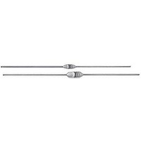
IR02BHR39K Vishay, IR02BHR39K Datasheet - Page 3

IR02BHR39K
Manufacturer Part Number
IR02BHR39K
Description
Common Mode Inductors 0.39uH 10%
Manufacturer
Vishay
Series
IRr
Datasheet
1.IR02BH8R2K.pdf
(4 pages)
Specifications of IR02BHR39K
Inductance
390 nH
Self Resonant Frequency
365 MHz
Core Material
Epoxy Conformal Coated
Dimensions
3.05 mm Dia. x 6.6 mm L
Product
Inductors
Test Frequency
25 MHz
Tolerance
10 %
Maximum Dc Current
700 mAmps
Maximum Dc Resistance
0.3 Ohms
Q Minimum
30
Operating Temperature Range
- 55 C to + 125 C
Termination Style
Axial
Inductance Tolerance
± 10%
Dc Current Rating
700mA
Q Factor
30
Inductor Type
Standard
Terminal Type
Axial Leaded
Current Rating
700mA
Body Material
Phenolic
Lead Free Status / RoHS Status
Lead free / RoHS Compliant
Lead Free Status / RoHS Status
Lead free / RoHS Compliant
Notes
(1)
(2)
Document Number: 34054
Revision: 15-Jul-09
STANDARD ELECTRICAL SPECIFICATIONS
MODEL
IR-4
IR-4
IR-4
IR-4
IR-4
IR-4
IR-4
IR-4
IR-4
IR-4
IR-4
IR-4
IR-4
IR-4
IR-4
IR-4
IR-4
IR-4
IR-4
IR-4
IR-4
IR-4
IR-4
IR-4
IR-4
IR-4
IR-4
IR-4
IR-4
IR-4
IR-4
IR-4
IR-4
IR-4
IR-4
IR-4
IR-4
IR-4
IR-4
IR-4
IR-4
IR-4
IR-4
IR-4
IR-4
IR-4
IR-4
IR-4
IR-4
IR-4
IR-4
IR-4
ORDERING INFORMATION
GLOBAL PART NUMBER
Measured with full length lead
Rated DC Current based on maximum temperature rise as shown in table
MODEL
IR-2
I
1000.0
1100.0
1200.0
1300.0
1500.0
1600.0
1800.0
100.0
110.0
120.0
130.0
150.0
160.0
180.0
200.0
220.0
240.0
270.0
300.0
330.0
360.0
390.0
430.0
470.0
510.0
560.0
620.0
680.0
750.0
820.0
910.0
IND.
(μH)
10.0
12.0
15.0
18.0
22.0
27.0
33.0
36.0
39.0
43.0
47.0
51.0
56.0
62.0
68.0
75.0
82.0
91.0
5.6
6.8
8.2
R
MODEL
INDUCTANCE VALUE
0
TOL.
± 10
± 10
± 10
± 10
± 10
± 10
± 10
± 10
± 10
± 10
10 μH
(%)
± 5
± 5
± 5
± 5
± 5
± 5
± 5
± 5
± 5
± 5
± 5
± 5
± 5
± 5
± 5
± 5
± 5
± 5
± 5
± 5
± 5
± 5
± 5
± 5
± 5
± 5
± 5
± 5
± 5
± 5
± 5
± 5
± 5
± 5
± 5
± 5
± 5
± 5
± 5
± 5
± 5
± 5
2
MIN.
45
50
50
55
65
65
75
75
60
65
60
60
60
55
55
55
55
55
55
50
50
50
60
65
65
65
65
65
65
65
65
65
65
65
65
65
65
65
65
65
65
55
55
55
55
55
30
30
30
30
30
30
Q
For technical questions, contact:
Inductors, Epoxy Conformal Coated,
Uniform Roll Coated, Axial Leaded
INDUCTANCE TOLERANCE
TEST FREQUENCY L AND Q
PACKAGE CODE
E
± 10 %
(MHz)
R
0.79
0.79
0.79
0.79
0.79
0.79
0.79
0.79
0.25
0.25
0.25
0.25
0.25
0.25
0.79
0.79
0.79
0.79
0.79
0.79
0.79
0.79
0.79
0.79
0.79
0.79
0.79
0.79
0.79
0.79
7.9
7.9
7.9
7.9
2.5
2.5
2.5
2.5
2.5
2.5
2.5
2.5
2.5
2.5
2.5
2.5
2.5
2.5
2.5
2.5
2.5
2.5
magnetics@vishay.com
PACKAGE CODE
INDUCTANCE VALUE
1
SRF MIN.
ER
(MHz)
60.0
55.0
50.0
45.0
42.0
40.0
34.0
30.0
25.0
19.0
15.5
14.5
13.7
13.0
12.7
12.0
11.5
11.0
10.5
10.3
10.0
9.5
8.9
8.7
8.5
8.0
7.5
7.0
6.5
6.2
5.9
5.7
5.4
5.1
4.8
4.5
4.2
3.9
3.7
3.5
3.3
3.1
2.9
2.7
2.5
2.3
2.1
2.0
1.9
1.8
1.7
1.6
0
(1)
0
DCR MAX.
JEDEC LEAD (Pb)-FREE STANDARD
32.0
0.50
0.60
0.90
1.10
1.40
2.25
2.50
2.60
2.50
2.60
2.70
2.75
2.85
3.15
3.30
3.70
3.90
4.30
4.50
4.90
5.20
5.45
6.05
6.40
6.75
7.10
7.45
7.80
11.0
11.5
12.0
15.5
16.3
17.1
17.9
18.8
24.7
25.9
27.2
28.6
30.0
31.5
33.1
43.5
45.7
49.0
52.5
54.0
56.7
(Ω)
3.0
3.0
INDUCTANCE TOLERANCE
RATED DC CURRENT
e2
Vishay Dale
K
495
395
360
290
265
240
185
175
170
165
180
176
172
170
167
164
160
156
147
143
136
133
128
124
121
114
111
108
106
103
101
129
125
123
108
105
102
100
(mA)
98
85
83
81
79
77
76
74
64
63
61
59
58
56
www.vishay.com
(2)
IR
3


