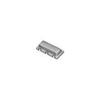
CSTCR6M00G53-R0 Murata, CSTCR6M00G53-R0 Datasheet - Page 14

CSTCR6M00G53-R0
Manufacturer Part Number
CSTCR6M00G53-R0
Description
Resonators 6.00MHz 0.5%
Manufacturer
Murata
Series
CSTCR-Gr
Datasheets
1.CSTCW20M0X53-R0.pdf
(32 pages)
2.CSTCE20M0V53-R0.pdf
(1 pages)
3.CSTCC2M00G56-R0.pdf
(21 pages)
4.CSTCR6M00G53-R0.pdf
(8 pages)
Specifications of CSTCR6M00G53-R0
Tolerance
0.5 %
Termination Style
SMD/SMT
Operating Temperature Range
- 20 C to + 80 C
Dimensions
2 mm W x 4.5 mm L x 1.5 mm H
Frequency Stability
0.2 %
Frequency
6 MHz
Lead Free Status / RoHS Status
Lead free / RoHS Compliant
Available stocks
Company
Part Number
Manufacturer
Quantity
Price
Company:
Part Number:
CSTCR6M00G53-R0
Manufacturer:
MURATA
Quantity:
9 000
3
Electrical Specifications of MHz Band Lead
CERALOCK
Electrical specifications of CSTLS series are shown in
the tables. Please note that oscillation frequency
measuring circuit constants of the CSTLS □G56 series
(with H-CMOS IC) depends on frequency.
MHz band three-terminal CERALOCK
is built-in load capacitance.
Fig. 3-1 shows the electrical equivalent circuit.
The table shows the general specifications of the CSTLS
series. Input and output terminals of the three-terminal
CERALOCK
of CERALOCK
But connecting reverse, the oscillating characteristics
are not affected except that the frequency has a slight
lag.
12
The frequency stability of CERALOCK
of crystal and LC or RC oscillators. Temperature
stability is ±0.3 to ±0.5% against initial values within
-20 to +80°C. The initial frequency precision is
±0.5% for standard products. The frequency of the
standard CERALOCK
measuring circuit, but the oscillation frequency may
shift when used in the actual IC circuit. Usually, if the
frequency precision needed for clock signal of a 1 chip
microcomputer is approximately ±2 to 3% under
working conditions, CERALOCK
used in most cases. If exact oscillation frequency is
required for a special purpose, Murata can manufacture
the ceramic resonator for the desired frequency.
The following are the general electrical specifications of
CERALOCK
oscillation frequency, please refer to the next chapter
“Application to Typical Oscillation Circuits”.)
Note
1. Electrical Specifications
3
• Please read rating and
• This catalog has only typical specifications because there is no space for detailed specifications. Therefore, please review our product specifications or consult the approval sheet for product specifications before ordering.
Specifications of CERALOCK
®
®
. (As for the standard measuring circuit of
®
are shown in the table titled Dimensions
®
(CSTLS Series)
CSTLS series in Chapter 1 on page 6.
CAUTION (for storage, operating, rating, soldering, mounting and handling) in this catalog to prevent smoking and/or burning, etc.
®
is adjusted by the standard
®
standard type can be
®
®
is between that
(CSTLS Series)
■
Resonant Impedance Specifications of
CSTLS/ Series
Fig. 3-1 Symbol for the Three-Terminal CERALOCK
CSTLS□G
CSTLS □X
Type
Frequency Range (MHz) Resonant Impedance (Ω max.)
13.40 — 03.99
14.00 — 07.99
18.00 — 10.00
16.00 — 32.99
33.00 — 50.00
CSTLS Series
®
150
130
125
150
140
®
P17E.pdf
SEP.16,
2011


