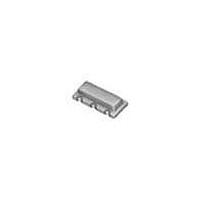
CSTCR4M91G53-R0 Murata, CSTCR4M91G53-R0 Datasheet - Page 3

CSTCR4M91G53-R0
Manufacturer Part Number
CSTCR4M91G53-R0
Description
Resonators 4.91MHz 0.5%
Manufacturer
Murata
Series
CSTCR-Gr
Datasheet
1.CSTCR4M91G53-R0.pdf
(12 pages)
Specifications of CSTCR4M91G53-R0
Tolerance
0.5 %
Termination Style
SMD/SMT
Operating Temperature Range
- 20 C to + 80 C
Dimensions
2 mm W x 4.5 mm L x 1.5 mm H
Frequency Stability
0.2 %
Frequency
4.91 MHz
Frequency Tolerance
± 0.5%
Resonant Impedance
60ohm
Oscillator Mounting
SMD
No. Of Pins
3
Length/height, External
1.15mm
Rohs Compliant
Yes
External Width
4.5mm
External Depth
2mm
Lead Free Status / RoHS Status
Lead free / RoHS Compliant
Available stocks
Company
Part Number
Manufacturer
Quantity
Price
Company:
Part Number:
CSTCR4M91G53-R0
Manufacturer:
MURATA
Quantity:
12 000
仕様書番号
Drawing No. JGC42-4247A
5.
機械的性能 Physical Characteristics
5-1 耐落下衝撃
5-2 耐振動性
5-3 基板たわみ強度
Random Drop
Vibration
Resistance
Bend Strength
PCB
項 目
Item
株式会社 村 田 製 作 所
1.0mの高さから木板床面に3回自然落下させた
後測定する。
Components shall be measured after 3 times
random dropping on the wooden plate from the
height of 1.0m.
振動周波数10~55Hz、全振幅1.5mmの振動を
X,Y,Zの3方向に各2時間加えた後測定する。
Applying the vibration of amplitude 1.5mm and
vibration frequency 10 to 55Hz in each of 3
perpendicular directions for 2 hours.
下図に示す様に加圧し、1回1秒の割合で5回加
圧する。
After components soldered on PCB, the load
shall be applied to the PCB as shown in below
figure for 5 times (1 second per 1 time).
基板厚み / PCB thickness : 1.6mm
単位 / unit : mm
φ
φ
5 Supporter
5
支持台
R10
20
加圧棒
Stick
10
Test Condition
試 験 条 件
部品
Part
45
Load
加圧
Murata Manufacturing Co.,Ltd.
±
±
1 Off-Center
1
センターズレ
45
PCB
Deflection
たわみ
外観に異常がなく、表
1 及 び 4-3 を 満 足 し ま
す。
No visible damage and
the measured values
shall meet Table 1 and
4-3.
表1及び4-3を満足しま
す。
The measured values
shall meet Table 1 and
4-3.
表1及び4-3を満足しま
す。
The measured values
shall meet Table 1 and
4-3.
試験後の規格
Specification
After Test
P. 3/12


