150D225X9035B2BE3 Vishay, 150D225X9035B2BE3 Datasheet - Page 9
150D225X9035B2BE3
Manufacturer Part Number
150D225X9035B2BE3
Description
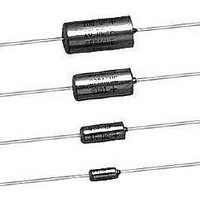
Tantalum Capacitors - Solid Leaded 2.2uF 35volts 10% B case
Manufacturer
Vishay
Series
150Dr
Datasheet
1.150D396X9010B2.pdf
(10 pages)
Specifications of 150D225X9035B2BE3
Voltage Rating
35 Volts
Termination Style
Axial
Operating Temperature Range
- 55 C to + 85 C
Dimensions
4.7 mm Dia. x 12.04 mm L
Dissipation Factor Df
4
Product
Tantalum Solid Hermetically Sealed
Capacitance
2.2 uF
Tolerance
10 %
Package / Case
Case B
Lead Free Status / RoHS Status
Lead free / RoHS Compliant


150D
Vishay Sprague
STANDARD REEL PACKAGING INFORMATION
1.
a. Component leads shall not be bent beyond 0.047"
b. The “C” dimension shall be governed by the overall
2. Orientation:
3. Reeling:
a. Components on any reel shall not represent more than
b. Component leads shall be positioned between pairs of
c. The disposable reels have hubs and corrugated
d. A minimum of 12.0" [304.8 mm] leader of tape shall be
e. 50 or 60 lb. Kraft paper must be wound between layer of
www.vishay.com
26
STANDARD REEL PACKAGING SPECIFICATIONS - MEETS EIA STANDARD RS-296 in inches [millimeters]
CODE
CASE
Component Leads:
[1.19 mm] maximum from their nominal position when
measured from the leading edge of the component lead
at the inside tape edge and at the lead egress from the
component.
length of the reel packaged component. The distance
between flanges shall be 0.125" to 0.250" [3.18 mm to
6.35 mm] greater than the overall component length.
All polarized components must be oriented to one
direction. The cathode lead tape shall be a color and the
anode lead tape shall be white.
two date codes when date code identification is required.
0.250" [6.35 mm] tape.
fibreboard flanges and core or equivalent.
provided before the first and after the last component on
the reel.
components as far as necessary for component
protection. Width of paper to be 0.062" to 0.250"
[1.57 mm to 6.35 mm] less than the “C” dimension
of the reel. Solid-Electrolyte T
Hermetically- Sealed, Axial-Lead.
A
B
R
S
I. D. REEL HUB
STANDARD REEL
0.625 ± 0.0062 DIA.
[15.88 ± 1.575]
[28.6 to 78.0]
1.126 to 3.07
THRU HOLE
13.0 [330.2]
0.135 ± 0.016
0.185 ± 0.016
0.289 ± 0.016
0.351 ± 0.016
[3.43 ± 0.41]
[4.70 ± 0.41]
[7.34 ± 0.41]
[8.92 ± 0.41]
TYPE 150D UNITS WITH
INSULATING SLEEVE
D
LABEL (4. a)
0.286 ± 0.031
0.474 ± 0.031
[12.04 ± 0.79]
0.686 ± 0.031
[17.42 ± 0.79]
0.786 ± 0.031
[19.96 ± 0.79]
[7.26 ± 0.79]
L
For technical questions, contact:
ANTALEX
“A”
“A”
Solid-Electrolyte T
Hermetically-Sealed, Axial-Lead
®
AWG NO.
Capacitors
24
24
22
22
LEAD SIZE
SECTION “A” - “A”
NOM. DIA.
0.750 [19.05]
ANTALEX
0.020
[0.51]
0.020
[0.51]
0.025
[0.64]
0.025
[0.64]
tantalum@vishay.com
f. A row of components must be centered between tapes
g. Staples shall not be used for splicing. Not more than
h. Quantity per reel shall be controlled so that tape
i. A maximum of 0.25 % of the components per reel
j. Adequate protection must be provided to prevent
4. Marking:
1.374 to 3.626
[34.9 to 92.1]
± 0.047" [1.19 mm]. In addition, individual components
may deviate from center of component row ± 0.031"
[0.79 mm].
4 layers of tape shall be used in any splice area and no
tape shall be offset from another by more than 0.031"
[0.79 mm] non-cumulative. Tape splices shall overlap at
least 6.0" [152.4 mm] for butt joints and at least 3.0"
[76.2 mm] for lap joints and shall not be weaker than
unspliced tape. Universal splicing clips may also be used.
components and cover shall not extend beyond the
smallest dimension of the flange (either across flats or
diameter). Once the quantity per reel for each part
number has been established, future orders for that part
number shall be packaged in that quantity. When order or
release quantity is less than the established quantity, a
standard commercial pack is to be used.
quantity may be missing without consecutive missing
components.
physical damage to both reel and components during
shipment and storage.
Minimum reel and carton marking shall consist of the
following: Customer Part Number, Purchase Order No.,
Quantity, Package Date, Manufacturer's Name, Electrical
Value, Date Code, Vishay Sprague Part Number and
Country of Origin.
®
COMPONENT
0.200 ± 0.015
0.200 ± 0.015
0.400 ± 0.015
[10.16 ± 0.38]
0.400 ± 0.015
[10.16 ± 0.38]
Capacitors
[5.08 ± 0.38]
[5.08 ± 0.38]
SPACING
A
B
BOTH SIDES (3. f)
TAPE SPACING
2.500 ± 0.062
2.500 ± 0.062
2.875 ± 0.062
[73.03 ± 1.57]
[73.03 ± 1.57]
2.875 ±0.062
[63.5 ± 1.57]
[63.5 ± 1.57]
0.031 [0.79] (3. f)
B
A
Document Number: 40015
TAPE SPACING
OFF CENTER (1. a)
COMPONENT
SPACING
0.031 [0.79] MAX.
0.125 [3.18] MAX.
0.250 [6.35] (3. b)
Revision: 14-Apr-10
PER REEL
UNITS
1000
1000
500
500
Related parts for 150D225X9035B2BE3
Image
Part Number
Description
Manufacturer
Datasheet
Request
R

Part Number:
Description:
357-036-542-201 CARDEDGE 36POS DL .156 BLK LOPRO
Manufacturer:
Vishay
Datasheet:
Part Number:
Description:
357-036-542-201 CARDEDGE 36POS DL .156 BLK LOPRO
Manufacturer:
Vishay
Datasheet:
Part Number:
Description:
357-036-542-201 CARDEDGE 36POS DL .156 BLK LOPRO
Manufacturer:
Vishay
Datasheet:
Part Number:
Description:
357-036-542-201 CARDEDGE 36POS DL .156 BLK LOPRO
Manufacturer:
Vishay
Datasheet:
Part Number:
Description:
357-036-542-201 CARDEDGE 36POS DL .156 BLK LOPRO
Manufacturer:
Vishay
Datasheet:
Part Number:
Description:
357-036-542-201 CARDEDGE 36POS DL .156 BLK LOPRO
Manufacturer:
Vishay
Datasheet:
Part Number:
Description:
357-036-542-201 CARDEDGE 36POS DL .156 BLK LOPRO
Manufacturer:
Vishay
Datasheet:
Part Number:
Description:
357-036-542-201 CARDEDGE 36POS DL .156 BLK LOPRO
Manufacturer:
Vishay
Datasheet:
Part Number:
Description:
357-036-542-201 CARDEDGE 36POS DL .156 BLK LOPRO
Manufacturer:
Vishay
Datasheet:
Part Number:
Description:
357-036-542-201 CARDEDGE 36POS DL .156 BLK LOPRO
Manufacturer:
Vishay
Datasheet:
Part Number:
Description:
357-036-542-201 CARDEDGE 36POS DL .156 BLK LOPRO
Manufacturer:
Vishay
Datasheet:
Part Number:
Description:
357-036-542-201 CARDEDGE 36POS DL .156 BLK LOPRO
Manufacturer:
Vishay
Datasheet:
Part Number:
Description:
357-036-542-201 CARDEDGE 36POS DL .156 BLK LOPRO
Manufacturer:
Vishay
Datasheet:
Part Number:
Description:
357-036-542-201 CARDEDGE 36POS DL .156 BLK LOPRO
Manufacturer:
Vishay
Datasheet:
Part Number:
Description:
357-036-542-201 CARDEDGE 36POS DL .156 BLK LOPRO
Manufacturer:
Vishay
Datasheet: