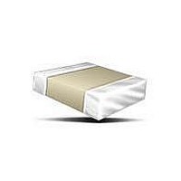
C0805C104M5UAC7210 Kemet, C0805C104M5UAC7210 Datasheet - Page 2

C0805C104M5UAC7210
Manufacturer Part Number
C0805C104M5UAC7210
Description
Multilayer Ceramic Capacitors (MLCC) - SMD/SMT 50volts 0.1uF Z5U 20%
Manufacturer
Kemet
Series
C0805r
Datasheet
1.C0805C104M5UAC7210.pdf
(16 pages)
Specifications of C0805C104M5UAC7210
Voltage Rating
50 Volts
Operating Temperature Range
+ 10 C to + 85 C
Temperature Coefficient / Code
Z5U
Product
General Type MLCCs
Dimensions
1.25 mm W x 2 mm L
Termination Style
SMD/SMT
Capacitance
0.1 uF
Tolerance
20 %
Package / Case
0805 (2012 metric)
Lead Spacing
0.75 mm
Lead Free Status / RoHS Status
Lead free / RoHS Compliant
Surface Mount Multilayer Ceramic Chip Capacitors (SMD MLCCs) – Z5U Dielectric, 50VDC-100VDC (Commercial Grade)
Dimensions – Millimeters (Inches)
Qualification/Certification
Commercial grade products are subject to internal qualification. Details regarding test methods and conditions are referenced in Table
4, Performance and Reliability.
Environmental Compliance
Pb-Free and RoHS compliant
Electrical Parameters/Characteristics
Regarding Aging Rate: Capacitance measurements (including tolerance) are indexed to a referee time of 48 or 1000 Hours. Please refer to a part number specific
datasheet for referee time details.
To obtain IR limit, divide MΩ-µF value by the capacitance and compare to GΩ limit. Select the lower of the two limits.
Note: When measuring capacitance it is important to ensure the set voltage level is held constant. The HP4284 & Agilent E4980 have a feature known as
Automatic Level Control (ALC). The ALC feature should be switched to "ON".
© KEMET Electronics Corporation • P.O. Box 5928 • Greenville, SC 29606 (864) 963-6300 • www.kemet.com
Capacitance and Dissipation Factor (DF) measured under the following conditions:
Code
Size
Capacitance Change with Reference to +25°C and 0 Vdc Applied (TCC)
0805
1206
1210
1825
2225
EIA
1812
1kHz ± 50Hz and 1.0 ± 0.2 Vrms if capacitance ≤10µF
120Hz ± 10Hz and 0.5 ± 0.1 Vrms if capacitance >10µF
Metric
Code
Size
4532
4564
5664
2012
3216
3225
2.00 (.079) ± 0.20 (.008) 1.25 (.049) ± 0.20 (.008)
3.20 (.126) ± 0.20 (.008) 1.60 (.063) ± 0.20 (.008)
3.20 (.126) ± 0.20 (.008) 2.50 (.098) ± 0.20 (.008)
5.60 (.220) ± 0.40 (.016) 6.40 (.248) ± 0.40 (.016)
4.50 (.177) ± 0.30 (.012) 3.20 (.126) ± 0.30 (.012)
4.50 (.177) ± 0.30 (.012) 6.40 (.252) ± 0.40 (.016)
Dissipation Factor (DF) Maximum Limits @ 25ºC
Aging Rate (Max % Cap Loss/Decade Hour)
Length
Insulation Resistance (IR) Limit @ 25°C
Item
L
Dielectric Withstanding Voltage
Operating Temperature Range
Width
W
Thickness
-10°C to +85°C
+22%, -56%
7.0%
250% of rated voltage
(5 ± 1 seconds and charge/discharge not exceeding 50mA)
4.0%
100 megohm microfarads or 10GΩ
(Rated voltage applied for 120 ± 5 secs @ 25°C)
T
0.50 (0.02) ± 0.25 (.010)
0.50 (0.02) ± 0.25 (.010)
0.50 (0.02) ± 0.25 (.010)
0.60 (.024) ± 0.35 (.014)
0.60 (.024) ± 0.35 (.014)
0.60 (.024) ± 0.35 (.014)
Bandwidth
T
Parameters/Characteristics
B
W
S
L
Separation
0.75 (.030)
B
Min.
N/A
S
C1004_Z5U • 5/27/2011
Electrodes
Solder Reflow Only
Solder Wave or
Solder Reflow
Conductive Metalization
Technique
Mounting
100% Tin or SnPb Plate
Nickel Plate
2


