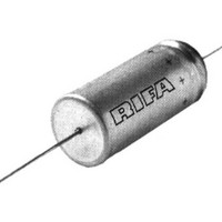
C410C100J1G5TA Kemet, C410C100J1G5TA Datasheet - Page 8

C410C100J1G5TA
Manufacturer Part Number
C410C100J1G5TA
Description
Multilayer Ceramic Capacitors (MLCC) - Leaded 100volts 10pF 5%
Manufacturer
Kemet
Series
C410r
Specifications of C410C100J1G5TA
Voltage Rating
100 Volts
Termination Style
Axial
Operating Temperature Range
- 55 C to + 125 C
Product
Conformally Coated MLCCs
Dimensions
2.54 mm Dia. x 4.32 mm L
Capacitance
10 pF
Tolerance
5 %
Temperature Coefficient
C0G (NP0)
Dielectric Characteristic
COG (NPO)
Material, Element
Ceramic
Termination
Axial
Voltage, Rating
100 VDC
Working Voltage
C0G - 50 & 100 X7R - 50 & 100 Z5U - 50& 100
Lead Free Status / RoHS Status
Lead free / RoHS Compliant
Ceramic Radial
Lead Tape and Reel Packaging
KEMET offers standard reeling of Molded and Conformally
Coated Radial Leaded Ceramic Capacitors for automatic
insertion per EIA specification RS-468. Parts are taped to a
tagboard carrier strip, and wound on a reel as shown in
Figure 1. Kraft paper interleaving is inserted between the
layers of capacitors on the reel. Ammopack is also available,
with the same lead tape configuration and package quantities.
Figure 3: Standard Reel
Figure 2: Lead Tape Configuration (See Table Below)
(1) Measured at the egress from the carrier tape, on the component side.
(2) Determined by a 4 digit suffix placed at the end of the part number, as follows:
40
Sprocket Hole Diameter
Sprocket Hole Pitch
Component Pitch
Lead Spacing (1)
Sprocket Hole Center
to Lead Center (1)
Sprocket Hole Center
to Component Center
Height to Seating Plane
(straight leads) (2)
Component Height
Above Tape Center
7301 =
7303 =
Dimension
H
1
Recommended for parts with formed leads.
Recommended for parts with straight leads.
D
0
© KEMET Electronics Corporation, P.O. Box 5928, Greenville, S.C. 29606, (864) 963-6300
C315*
C320*
Ceramic Radial Tape and Reel Dimensions in Millimeters & (Inches)
H
F
Symbol
Do
P0
P1
P2
H1
P
H
F
C330**
C340**
C6xx#
.655" 0.010"
(16.6 0.25)
(30.48 cm)
12"
16.0 (.630) 18.0 (.709)
(.150)
3.81
7301
5.08
(.20)
12.7 (.500)
12.7 (.500)
6.35 (.250)
32.2 (1.27)
Nominal
mm (inch)
4.0 (.157)
C056**
C066**
(.10)
(.200)
7303
2.54
5.08
*
(82.6)
3
1
/
Example: C322C104K5R5CA7301
Example: C320C104K5R5CA7303
4
"
0.5 (.020) Minimum
CKR06**
7301
CK06**
.059" to .315"
Greater Than
C062**
Components
(+.024 -.008)
Tolerance
mm (inch)
(3.18)
of Taped
Maximum
Over All
1 /
+0.6 -0.2
Height
0.2 (.008)
0.3 (.012)
0.3 (.012)
0.7 (.028)
1.3 (.051)
8 "
Hub
PACKAGING INFORMATION
7303
CERAMIC LEADED
CKR05**
CK05**
C052**
Adhesive Tape
Height to Seating
Plane (formed leads) (2)
Component Alignment
Lead Protrusion
Composite Tape
Thickness
Overall Tape and
Lead Thickness
Carrier Tape Width
Hold-Down Tape
Width
Hold-Down Tape
Location
T
Dimension
P
P1
P
C317**
C322**
C323**
2
H
0
Carrier Tape
Figure 1
Carrier Strip
Symbol
C6xx#
C333**
H
L1
t
T
W
W0
W2
h
0
P
L
0
1
16.0 (.630) 18.0 (.709)
7301
Nominal
mm (inch)
18.0 (.709)
4.0 (.157)
1.0 (.039)
0.7 (.051)
1.5 (.059)
5.0 (.197)
3.0 (.118)
* Lead spacings are 2.54mm
** Lead spacings are 5.08mm
# See page 15 for exact lead
(Note: Non-standard lead lengths
(.10") center-to-center.
(.20") center-to-center.
configuration for Series.
W
W
W
available in bulk only.)
7303
2
2
0
Interleaving
Kraft Paper
W
0.5 (.020) Minimum
7301
(+.039 -.020)
Tolerance
mm (inch)
Maximum
Maximum
+1.0 - 0.5
Maximum
Minimum
0.2 (.008)
0.2 (.008)
7303
Tape
Carrier
1MM Max.
(.039")
H


