JR13WCCA-7(71) Hirose Electric Co Ltd, JR13WCCA-7(71) Datasheet - Page 7
JR13WCCA-7(71)
Manufacturer Part Number
JR13WCCA-7(71)
Description
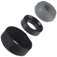
CONN STRAIN RELIEF JR13 7POS
Manufacturer
Hirose Electric Co Ltd
Series
JR-Wr
Datasheet
1.JR13WCCA-4.pdf
(8 pages)
Specifications of JR13WCCA-7(71)
Accessory Type
Strain Relief
Shell Size - Insert
13
Features
Self Tightening
Color
Black
For Use With/related Products
JR-W and RM-W Series Connectors
For Use With
RM15WTPZ-8S(71) - CONN PLUG 8POS W/SOCKET INSERTRM15WTPZ-8P(71) - CONN PLUG 8POS W/PIN INSERTRM15WTPZ-4S(71) - CONN PLUG 4POS W/SOCKET INSERTRM15WTPZ-4P(71) - CONN PLUG 4POS W/PIN INSERTRM15WTPZ-2S(71) - CONN PLUG 2POS W/SOCKET INSERTRM15WTPZ-2P(71) - CONN PLUG 2POS W/PIN INSERTRM15WTPZ-12S(71) - CONN PLUG 12POS W/SOCKET INSERTRM15WTPZ-12P(71) - CONN PLUG 12POS W/PIN INSERTRM15WTPZ-10S(71) - CONN PLUG 10POS W/SOCKET INSERTRM15WTPZ-10P(71) - CONN PLUG 10POS W/PIN INSERTRM15WTLP-12P(71) - CONN PLUG 12POS W/PIN INSERT R/AHR1320 - CONN PLUG WATERPROOF 5POS FMALEHR1319 - CONN PLUG WATERPROOF 3POS FMALEHR1309 - CONN PLUG WATERPROOF 5POS MALEHR1308 - CONN PLUG WATERPROOF 3POS MALE
Lead Free Status / RoHS Status
Lead free / RoHS Compliant
Other names
*JR13WCCA-7(71)
HR1378
HR1378


144
JR-W Series●IP67 waterproof protected heavy duty metal shell connectors
■Plug assemblies procedure
Table 1(Solder type)
■Work procedure
1.Disassembly of connector
(1)To remove the plug, remove the set screw, fi t a receptacle adaptive to the P shell unit to fi x, and remove he cord tube.
(2)To remove the cord clamp, remove the cord tightening screws.
2.Connection
2.1 Soldering type
(1) Use the cable so that the conductor can be soldered properly into the solder cup with the cable sheath diameter adaptive to each cord
(2) After the terminal treatment of the cable with a size given in Table 1, thread on the ccable the clamp, washer, gasket, cord tube and
(3) Solder to connect the conductors to the terminals of the P shell unit. Shrinkable tube is recommended to be used at the connecting
3.Assembly of connector
(1)Fit the connected P shell unit to the receptacle fi xed with a vice or the like. Torque the cord tube to the level as given in Table3.
(2) Fit the gasket, washer and clamp. Torque the clamp to the level as given in Table3 while preventing the cable from being ratated. And,
(3)Torque the set screw to 0.2 to 0.25 N·m.
(4)Torque the cord tightening screw(two positions) to 0.65 to 0.7 N·m.(Note 4)
Shell size
Note2. keep the size until assembling is completed
Note3. After tightening, check water proof performance before using.
Note4. Check the clamp strenrth before using.
clamp.
coupling in this order and direction as shown above.
part because insulating performance might deteriorate due to solder whiskers or dewing. After connecting, adjust to meet the C size.
(Note2)
Loctite Japan Co Ltd. is recommended to be applied as locking.(Note3)
13
16
21
25
(3)
(3)
(3)
(3)
A
(12)
(14)
(17)
(20)
B
37 or below
39 or below
42 or below
37 or below
C
[Unit:mm]
Table 2
Shell size
13
16
21
25
Tightning torque[Unit:N·m]
2 to 2.5
3 to 3.5
4 to 4.5
5 to 5.5
C
Related parts for JR13WCCA-7(71)
Image
Part Number
Description
Manufacturer
Datasheet
Request
R

Part Number:
Description:
CONN STRAIN RELIEF JR13 4POS
Manufacturer:
Hirose Electric Co Ltd
Datasheet:

Part Number:
Description:
CONN STRAIN RELIEF JR13 6POS
Manufacturer:
Hirose Electric Co Ltd
Datasheet:

Part Number:
Description:
CONN STRAIN RELIEF JR13 10POS
Manufacturer:
Hirose Electric Co Ltd
Datasheet:

Part Number:
Description:
CONN STRAIN RELIEF JR13 5POS
Manufacturer:
Hirose Electric Co Ltd
Datasheet:

Part Number:
Description:
CONN STRAIN RELIEF JR13 8POS
Manufacturer:
Hirose Electric Co Ltd
Datasheet:

Part Number:
Description:
Conn Rectangular PL 14 POS 2.54mm Crimp RA Cable Mount
Manufacturer:
Hirose Electric Co Ltd
Part Number:
Description:
Conn Shrouded Header HDR 10 POS 2mm Solder ST SMD Embossed T/R
Manufacturer:
Hirose Electric Co Ltd
Datasheet:
Part Number:
Description:
DF11-20DP-2DSA(24)
Manufacturer:
Hirose Electric Co Ltd
Datasheet:
Part Number:
Description:
Conn Shrouded Header HDR 6 POS 2mm Solder ST Thru-Hole Bag
Manufacturer:
Hirose Electric Co Ltd
Datasheet:
Part Number:
Description:
Conn Shrouded Header HDR 8 POS 2mm Solder ST Thru-Hole Tube
Manufacturer:
Hirose Electric Co Ltd
Datasheet:
Part Number:
Description:
Conn Shrouded Header HDR 26 POS 2mm Solder ST SMD
Manufacturer:
Hirose Electric Co Ltd
Datasheet:
Part Number:
Description:
Conn Shrouded Header HDR 22 POS 2mm Solder ST SMD
Manufacturer:
Hirose Electric Co Ltd
Part Number:
Description:
Conn Shrouded Header HDR 22 POS 2mm Solder ST SMD
Manufacturer:
Hirose Electric Co Ltd
Part Number:
Description:
2mm 22w Wire to Board IDC Crimp Connector
Manufacturer:
Hirose Electric Co Ltd