1669-01 Bourns Inc., 1669-01 Datasheet
1669-01
Manufacturer Part Number
1669-01
Description
Gas Discharge Tubes (GDTs) / Gas Plasma Arrestors 1200pF Double Ended
Manufacturer
Bourns Inc.
Series
1669r
Datasheet
1.1669-02.pdf
(2 pages)
Specifications of 1669-01
Peak Pulse Current
20 KA
Dc Breakover Voltage (nominal)
36 V
Number Of Electrodes
3
Termination Style
Radial
Failsafe Protection Y/n
N
Dimensions
3.94 mm L
Mounting Style
Through Hole
Technology
Gas Discharge Tube
Voltage Rating
36 V
Lead Free Status / RoHS Status
Lead free / RoHS Compliant


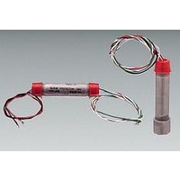
Used for full weather protection of fi eld transmitters and instrumentation operating on 24-28 V systems, the 1669 Series protects
sensitive I/O circuitry from surges of any polarity or magnitude. Principal use is on 4-20 mA control loops and can be used on
grounded (+ or -) or ungrounded circuits. Able to survive and protect even from direct lightning strikes to the transmitter ground or
fi eld wiring. Automatic recovery after passage of the surge. Long life, high operational reliability.
Construction is hybrid 3-stage design, using a high surge capacity Balanced Trigard
and silicon suppressors to provide differential and common mode protection with very low clamping levels for delicate loads. The
housing is thick walled schedule 40, type 303 stainless steel. Wiring is #20 (.5 mm
are used for the input; striped colors signify the protected output. The protector ground wire (green) is electrically bonded to the
metallic housing; it is for connection to the grounding screw within the fi eld device. Use Model 1669-02/06 for standard ground
resistance conditions.
Use Model 1669-01 / 05 with higher voltage isolation to ground for sites with high resistance soil conditions or where signifi cant
ground potential differences are known to exist.
Warranty ...................................................................................3 years ................................................. 3 years
Maximum Signal Voltage ..........................................................30 Vpk ................................................. 30 Vpk
DC Clamping Voltage
Capacitance, 1 MHz, max
Series Resistance, per line .......................................................22 Ω ..................................................... 22 Ω
Inductance, per line, max ........................................................1 µH ..................................................... 1 µH
DC Leakage, 24 Vdc, max ........................................................1 µA ..................................................... 1 µA
Impulse Clamping Voltage: L-L ................................................50 V ..................................................... 50 V
Ambient Temperature Range, Storage .....................................65 °C to +130 °C ................................. 65 °C to +130 °C
Operating Temperature
Maximum Load Current ............................................................150 mA ................................................ 150 mA
Humidity ...................................................................................0 - 95 % Condensing .......................... 0 - 95 % Condensing
Altitude, Operating ...................................................................6,000 m ............................................... 6,000 m
Weight
Component Response Time .....................................................1 ns ...................................................... 1 ns
Surge Life (L+L)-G
Characteristics
L-L .......................................................................................36 V ..................................................... 36 V
L-G ......................................................................................250 V ................................................... 36 V
L-L .......................................................................................1200 pF ............................................... 2000 pF
L-G ......................................................................................40 pF ................................................... 2000 pF
1 kA (L+L)-G, 10/1000 µs, 500 V/µs: L-G ..........................750 V ................................................... 70 V
Non-hazardous areas..........................................................40 °C to +100 °C ................................. 40 °C to +100 °C
Hazardous areas .................................................................20 °C to + 55 °C .................................. 20 °C to + 55 °C
- Except when limited for T5 conditions (.73 W ..................129 mA ................................................ 129 mA
1669-01 / 02 .......................................................................150 g ................................................... 150 g
1669-05 / 06 .......................................................................220 g ................................................... 220 g
20 kA 8/20 µs ......................................................................20 times ............................................... 20 times
1 kA 10/1000 µs ..................................................................1000 times ........................................... 1000 times
Features
■
■
■
■
1669 Series – Transient Protector
Fits single or dual conduit ports
Weatherproof
Long life, high operational reliability
Stainless steel construction
Model 1669-01
Model 1669-05
Customers should verify actual device performance in their specifi c applications
2
) 1000 V, PVC insulated. Solid red and black colors
®
Gas Tube protector, coordination impedance
Specifi cations are subject to change without notice.
Model 1669-02
Model 1669-06
Related parts for 1669-01
Image
Part Number
Description
Manufacturer
Datasheet
Request
R

Part Number:
Description:
SIGNAL PROTECT FIELD
Manufacturer:
Bourns Inc.
Datasheet:

Part Number:
Description:
Surge Suppressors 2000pF Single Ended
Manufacturer:
Bourns Inc.
Datasheet:

Part Number:
Description:
Manufacturer:
Bourns, Inc.
Datasheet:
Part Number:
Description:
11mm Potentiometer
Manufacturer:
Bourns, Inc.
Datasheet:
Part Number:
Description:
Manufacturer:
Bourns, Inc.
Datasheet:
Part Number:
Description:
Manufacturer:
Bourns, Inc.
Datasheet:
Part Number:
Description:
Manufacturer:
Bourns, Inc.
Datasheet:
Part Number:
Description:
5/16 Round Trimming Potentiometer
Manufacturer:
Bourns, Inc.
Datasheet:
Part Number:
Description:
4100R Series: Thick Film Moulded DIPs - Resistor Networks
Manufacturer:
Bourns, Inc.
Datasheet:
Part Number:
Description:
PROTECTOR - SINGLE BIDIRECTIONAL
Manufacturer:
Bourns, Inc.
1669-01 Summary of contents
Page 1
... Use Model 1669-02/06 for standard ground resistance conditions. Use Model 1669- with higher voltage isolation to ground for sites with high resistance soil conditions or where signifi cant ground potential differences are known to exist. ...
Page 2
... Installation Diagrams 1669-01, 1669-02 (For control room protector use 1820-28-A1/A3) 1669-05, 1669-06 (For control room protector ...