MS3420-4 Amphenol Industrial Operations, MS3420-4 Datasheet - Page 6
MS3420-4
Manufacturer Part Number
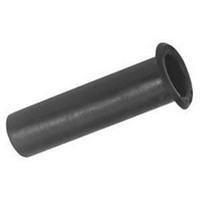
MS3420-4
Description
BUSHING TELESCOPING W/O FLANGE
Manufacturer
Amphenol Industrial Operations
Datasheet
1.97-79-513-8.pdf
(44 pages)
Specifications of MS3420-4
Accessory Type
Bushing, Telescoping
Features
Flange
Peak Reflow Compatible (260 C)
No
Leaded Process Compatible
No
Connector Type
Circular
For Use With
MS3057-A Style Cable Clamp
Lead Free Status / RoHS Status
Contains lead / RoHS non-compliant
Color
-
For Use With/related Products
Circular Connectors
Shell Size - Insert
-
Lead Free Status / RoHS Status
Contains lead / RoHS non-compliant, Contains lead / RoHS non-compliant


97 series solder type
insert availability
8S-1
10SL-3
10SL-4
12SL-844 *
12S-3
12-5
12S-6 *
14S-1†
14S-2
14S-4 †
14S-5
14S-6
14S-7
14S-9†
16S-1
16S-4
16S-5
16S-6 †
16-7
16S-8
16-9
16-10
16-11 †
16-12
16-13
18-1
18-3†
18-4
18-5
18-8
18-9
18-10†
18-11
18-12†
18-13
18-16
18-19†
18-20
18-22†
18-29 †
18-420*
20-3†
Insert Number
Contacts
Total
10
10
1
3
2
4
2
1
2
3
4
1
5
6
3
2
7
2
3
3
3
5
4
3
2
1
2
2
4
3
8
7
4
5
6
4
1
5
3
5
1
3
1/16
1/16
1/16
1/16
1/16
1/8
1/16
1/16
1/8
1/16
1/16
1/16
1/8
1/16
1/16
1/16
1/16
1/16
1/16
1/16
1/16
1/16
1/16
1/8
1/8
1/8
1/16
1/16
1/16
1.16
1/16
5/16
1/16
1/16
1/8
1/16
1/8
Inches
Mechanical
Spacing
1.57
1.57
1.57
1.57
1.57
3.18
1.57
1.57
3.18
1.57
1.57
1.57
3.18
1.57
1.57
1.57
1.57
1.57
1.57
1.57
1.57
1.57
1.57
3.18
3.18
3.18
1.57
1.57
1.57
1.57
1.57
7.92
1.57
1.57
3.18
1.57
3.18
mm
Service
INST.
INST.
INST.
INST.
Rating
INST.
INST
A
A
A
A
D
A
D
A
A
A
D
A
A
A
A
A
A
A
A
A
A
D
D
D
A
A
A
A
A
C
A
A
D
A
D
0
1
4
Contact Size
1
1
8
Thermo-
Hi-Volt-
couple
age**
12
1
2
3
2
2
2
2
1
2
4
5
3
1
1
3
Thermo-
couple
10
16
1
3
2
4
2
2
3
4
1
5
6
3
2
7
2
3
3
2
5
2
4
6
4
1
7
5
6
5
3
5
4
Not all insert arrangements are currently available for environmental individual
wire seal. Consult Amphenol, Sidney, NY for availability.
† Inactive for new military design, but available for replacement or for non-mili-
* “MS” number not assigned. Use “97” prefix in place of “MS” in completing cata-
** Hi-Voltage = 17KVAC/24KVDC
20-4
20-6†
20-7
20-8
20-11†
20-14
20-15
20-16
20-17
20-18
20-19†
20-21
20-23
20-24
20-27
20-29
20-33
22-1†
22-2
22-4†
22-5
22-8†
22-9
22-10
22-11
22-12
22-13†
22-14
22-15
22-16†
22-18
22-19
22-20†
22-22
22-23
Insert Number
tary purposes.
log number. See how to order, page 19.
Molded-in pin (MIP) insert requires (910) deviation. See how to order, pg. 19.
Contacts
Total
13
14
17
11
19
14
4
3
8
6
5
7
9
6
9
3
9
2
4
2
3
4
6
2
3
4
2
5
5
6
9
8
9
4
8
1/8
1/8
1/8
1/16
1/16
1/16
1/16
1/16
1/16
1/16
1/16
1/16
1/16
1/16
1/16
1/16
1/8
1/8
1/16
1/8
3/16
3/16
3/16
1/4
1/8
1/8
1/16
1/16
3/16
1/16
1/16
1/8
1/16
1/16
1/16
1/16
1/8
1/16
Inches
Mechanical
Spacing
3.18
3.18
3.18
1.57
1.57
1.57
1.57
1.57
1.57
1.57
1.57
1.57
1.57
1.57
1.57
1.57
3.18
3.18
1.57
3.18
4.75
4.75
4.75
6.35
3.18
3.18
1.57
1.57
4.75
1.57
1.57
3.18
1.57
1.57
1.57
1.57
3.18
1.57
mm
Service
Rating
INST.
INST.
D
D
D
A
A
A
A
A
A
A
A
A
A
A
A
A
D
D
A
D
E
E
E
B
D
D
A
A
E
A
A
D
A
A
A
A
D
A
0
4
Contact Size
2
2
3
2
2
2
3
2
2
4
8
12
4
3
7
2
5
3
1
2
2
2
3
4
5
3
1
7
13
14
17
11
19
14
16
3
4
4
4
7
1
6
8
2
4
4
2
3
1
1
6
5
3
9
Related parts for MS3420-4
Image
Part Number
Description
Manufacturer
Datasheet
Request
R

Part Number:
Description:
BUSHING TELESCOPING W/O FLANGE
Manufacturer:
Amphenol Industrial Operations
Datasheet:

Part Number:
Description:
MIL-C-5015 MS3420 BUSHINGS, BODY STYLE, TERMINATION, SHELL SIZE, INSERT ARRANGEMENT, GENDER, CONTACTS
Manufacturer:
Amphenol Industrial Operations

Part Number:
Description:
BUSHING TELESCOPING W/FLANGE
Manufacturer:
Amphenol Industrial Operations
Datasheet:
Part Number:
Description:
BUSHING TELESCOPING W/O FLANGE
Manufacturer:
Amphenol Industrial Operations
Datasheet:
Part Number:
Description:
STRAIN RLF 90 DEG 2.250-16 UNEF
Manufacturer:
Amphenol Industrial Operations
Datasheet:

Part Number:
Description:
JAM NUT CONN, RCPT, SIZE 9, 6POS, PANEL
Manufacturer:
Amphenol Industrial Operations
Datasheet:
Part Number:
Description:
PT 41C 41#20 PIN RECP
Manufacturer:
Amphenol Industrial Operations
Part Number:
Description:
PT 41C 41#20 SKT RECP
Manufacturer:
Amphenol Industrial Operations