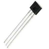
SS361CT Honeywell, SS361CT Datasheet - Page 2

SS361CT
Manufacturer Part Number
SS361CT
Description
Board Mount Hall Effect / Magnetic Sensors SOT-23 SMT Bi-polar Hall Effect
Manufacturer
Honeywell
Datasheet
1.SS361CT.pdf
(4 pages)
Specifications of SS361CT
Operational Type
Bipolar Latch
Operating Supply Voltage
4 V to 24 V
Supply Current
6 mA
Package / Case
SOT-23
Operating Point Min/max
5 G to 95 G
Maximum Operating Temperature
+ 125 C
Minimum Operating Temperature
- 40 C
Supply Voltage (min)
4 V
Supply Voltage (max)
24 V
Maximum Output Current
20 mA
Temperature Threshold
+ 150 C
Lead Free Status / RoHS Status
Lead free / RoHS Compliant
Table 1. SS361CT/SS461C Performance Specifications (At 4 Vdc to 24 Vdc supply, 20 mA load, T
[-40 ºF to 257 ºF] except where otherwise specified.
Table 2. SS361CT/SS461C Absolute Maximum Ratings
Note 1:
electrical and mechanical characteristics are not guaranteed as the maximum limits (above recommended operating conditions)
are approached, nor will the device necessarily operate at absolute maximum ratings.
Figure 1. Typical Magnetic Characteristics
2
and release) will be as specified in the magnetic characteristics. To test the switch against
the specified magnetic characteristics, the switch must be placed in a uniform magnetic
field.
Characteristic
Supply voltage
Supply current
Vsat
Output leakage current
Rise/fall time
Operate
Release
Differential
Operating temperature
Storage temperature
NOTICE
Bipolar Hall-effect sensor ICs may have an initial output in either the ON or OFF state if powered up with an applied magnetic
field in the differential zone (applied magnetic field >Brp and <Bop). Honeywell recommends allowing 10 µs for output voltage to
stabilize after supply voltage has reached 5 V.
NOTICE
The magnetic field strength (Gauss) required to cause the switch to change state (operate
Characteristic
Supply voltage
Applied output voltage
Output current
Magnetic flux
rise
fall
Absolute maximum ratings are the extreme limits that the device will withstand without damage to the device. However, the
www.honeywell.com/sensing
-40 °C to 125 °C [-40 °F to 257 °F]
-40 °C to 125 °C [-40 °F to 257 °F]
-40 °C to 125 °C [-40 °F to 257 °F]
-40 °C to 125 °C [-40 °F to 257 °F]
-40 °C to 85 °C [-40 °F to 185 °F]
-40 °C to 85 °C [-40 °F to 185 °F]
-40 °C to 85 °C [-40 °F to 185 °F]
Vsupply = 12 V at 25 °C [77 °F]
Vsupply = 5 V at 25 °C [77 °F]
Vsupply = 3 V at 25 °C [77 °F]
Vsupply = 4 Vdc to 24 Vdc
R
L
=1.6 KOhm, C
Gauss >95
Gauss >95
Condition
-26.0
Min.
-0.5
–
–
–
L
= 20 pF
1
Figure 2. Current Sinking Output Block Diagram
Typ.
–
–
–
–
-40 [-40]
-40 [-40]
Min.
-80
-95
50
50
4
–
–
–
–
–
–
–
5
–
5
Typ.
100
100
3.5
-50
-50
50
50
–
4
–
–
–
–
–
–
–
–
no limit
Max.
28.0
28.0
20
125 [257]
150 [302]
A
= -40 ºC to 125 ºC
Max.
160
190
0.4
1.5
1.5
1.5
24
10
80
95
-5
-5
6
5
8
Gauss
Unit
mA
V
V
°C [°F]
°C [°F]
Gauss
Gauss
Gauss
Unit
Vdc
mA
µA
µs
V


