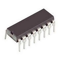
NTE955M NTE ELECTRONICS, NTE955M Datasheet - Page 2

NTE955M
Manufacturer Part Number
NTE955M
Description
Replacement Semiconductors DIP-8 18V TIMER
Manufacturer
NTE ELECTRONICS
Datasheet
1.NTE955M.pdf
(4 pages)
Specifications of NTE955M
Operating Mode
Astable / Monostable
No. Of Timers
1
Clock External Input
No
Supply Voltage Range
4.5V To 16V
Digital Ic Case Style
DIP
No. Of Pins
8
Operating Temperature Range
0°C To +70°C
Lead Free Status / RoHS Status
Lead free / RoHS Compliant
Lead Free Status / RoHS Status
Lead free / RoHS Compliant, Lead free / RoHS Compliant
Absolute Maximum Ratings: (T
Power Supply Voltage. V
Discharge Current (Pin7), I
Power Dissipation, P
Operating Temperature Range, T
Storage Temperature Range, T
Lead Temperature (During Soldering, 10sec), T
Electrical Characteristics: (T
Note 2. Supply current when output is high is typically 1mA less.
Note 3. Tested at V
Note 4. This will determine the maximum value of R
Operating Supply Voltage Range
Supply Current
Timing Error
Threshold Voltage
Trigger Voltage
Reset Voltage
Reset Current
Threshold Current
Discharge Leakage Current (Pin7)
Control Voltage Level
Output Voltage Low
Output Voltage High
Rise Time of Output
Fall Time of Output
Drift with Temperature
Drift with Supply Voltage
Initial Accuracy C = 0.1 F
Derate Above 25 C
R = 20M .
Parameter
CC
D
= 5V and V
. . . . . . . . . . . . . . . . . . . . . . . . . . . . . . . . . . . . . . . . . . . . . . . . . . . . . . . . . .
CC
7
. . . . . . . . . . . . . . . . . . . . . . . . . . . . . . . . . . . . . . . . . . . . . . . . . . . . . . .
. . . . . . . . . . . . . . . . . . . . . . . . . . . . . . . . . . . . . . . . . . . . . . . . . . . . . . . . . .
. . . . . . . . . . . . . . . . . . . . . . . . . . . . . . . . . . . . . . . . . . . . . . . . . . . . . .
stg
A
= +25 C, V
A
A
Symbol
CC
. . . . . . . . . . . . . . . . . . . . . . . . . . . . . . . . . . . . . . . . . . . . .
. . . . . . . . . . . . . . . . . . . . . . . . . . . . . . . . . . . . . . . . . .
V
t
t
= +25 C unless otherwise specified)
V
V
V
V
I
I
I
OLH
OHL
V
V
CC
I
TH
dis
CC
OH
TH
CL
OL
R
R
T
= 15V. Monostable mode.
R
Low State,
Note 2
R = 1k to 100k , Note 3
V
V
Note 4
V
V
V
V
V
V
CC
CC
CC
CC
CC
CC
CC
CC
L
CC
= ,
= 5V
= 15V
= 5V
= 15V
= 5V
= 15V
= 5V
= 15V
= 5V to 15V unless otherwise specified)
L
Test Conditions
. . . . . . . . . . . . . . . . . . . . . . . . . . . . . . . . . . . .
A
V
V
I
I
I
I
I
I
I
= R
SINK
SINK
SINK
SINK
SINK
SOURCE
SOURCE
CC
CC
= 5V
= 15V
B
= 5mA
= 10mA
= 50mA
= 100mA
= 200mA
for 15V operation. The maximum total
= 100mA
= 200mA
12.75
2.75
Min
4.5
0.4
2.6
9.0
–
–
–
–
–
–
–
–
–
–
–
–
–
–
–
–
–
–
–
0.667
1.67
3.33
0.25
13.3
12.5
Typ
100
100
3.0
1.0
0.1
5.0
0.7
0.1
0.1
0.1
0.4
2.0
2.5
3.3
10
50
10
–
–
–65 to +150 C
Max
0.25
0.35
0.25
0.75
100
6.0
1.0
4.0
2.5
16
15
11
0 to +70 C
–
–
–
–
–
–
–
–
–
–
–
–
–
5mW/ C
625mW
+260 C
ppm/ C
200mA
x V
Unit
%/V
mA
mA
mA
nA
ns
ns
%
V
V
V
V
V
V
V
V
V
V
V
V
V
V
A
CC
18V


