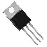
NTE263 NTE ELECTRONICS, NTE263 Datasheet - Page 2

NTE263
Manufacturer Part Number
NTE263
Description
Replacement Semiconductors TO-220 NPN DAR PWR
Manufacturer
NTE ELECTRONICS
Datasheet
1.NTE263.pdf
(2 pages)
Specifications of NTE263
Transistor Polarity
NPN
Collector Emitter Voltage V(br)ceo
100V
Power Dissipation Pd
65W
Dc Collector Current
10A
Dc Current Gain Hfe
20000
Operating Temperature Range
-65°C To +150°C
Lead Free Status / RoHS Status
Lead free / RoHS Compliant
Lead Free Status / RoHS Status
Lead free / RoHS Compliant, Lead free / RoHS Compliant
Electrical Characteristics: (T
Note 1. Pulse Test: Pulse Width
OFF Characteristics
Collector–Emitter Sustaining Voltage
Collector Cutoff Current
Emitter Cutoff Current
ON Characteristics (Note 1)
DC Current Gain
Collector–Emitter Saturation Voltage
Base–Emitter ON Voltage
Dynamic Characteristics
Small–Signal Current Gain
Output Capacitance
Small–Signal Current Gain
B
B
Parameter
NTE263
NTE264
C
V
Symbol
V
V
CEO(sus)
= +25 C unless otherwise specified)
C
E
C
E
I
I
CE(sat)
I
BE(on)
|h
C
CEO
h
CEX
EBO
h
FE
ob
fe
fe
300 s, Duty Cycle
|
I
V
V
V
V
I
I
I
I
I
I
I
V
I
C
C
C
C
C
C
C
C
C
CE
CE
CE
BE
CB
= 200mA, I
= 5A, V
= 10A, V
= 5A, I
= 10A, I
= 3A, V
= 10A, V
= 1A, V
= 1A, V
= 100V, V
= 5V, I
= 100V, I
= 100V, V
= 10V, I
B
CE
CE
CE
CE
B
.147 (3.75)
.070 (1.78) Max
C
= 0.01A
CE
CE
Test Conditions
Dia Max
= 0.1A
E
= 0
= 3V
= 3V
= 5V, f
= 5V, f = 1kHz
B
B
EB(off)
= 0, f = 1MHz
EB(off)
= 3V
= 3V
= 0
= 0, Note 1
.100 (2.54)
test
2%.
= 1.5V, T
Base
= 1.5V
= 1MHz
C
.420 (10.67)
= +125 C
Max
.250 (6.35)
1000
1000
Min
100
100
20
–
–
–
–
–
–
–
–
–
Max
Collector/Tab
Emitter
.110 (2.79)
(12.7)
(12.7)
Typ
.500
.500
Max
Min
–
–
–
–
–
–
–
–
–
–
–
–
–
–
20000
Max
300
200
1.0
2.8
4.5
–
3
5
–
2
3
–
–
Unit
mA
mA
mA
pF
V
V
V
V
V
A


