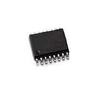
DG444DY-E3 Vishay, DG444DY-E3 Datasheet - Page 2

DG444DY-E3
Manufacturer Part Number
DG444DY-E3
Description
Analog Switch ICs SPST Analog Switch
Manufacturer
Vishay
Specifications of DG444DY-E3
Number Of Switches
Quad
Switch Configuration
SPST
On Resistance (max)
160 Ohms @ 10.8 V
On Time (max)
450 ns @ 12 V
Off Time (max)
200 ns @ 12 V
Supply Voltage (max)
25 V
Supply Current
0.000001 mA @ +/- 16.5 V
Maximum Power Dissipation
640 mW
Maximum Operating Temperature
+ 85 C
Mounting Style
SMD/SMT
Package / Case
SOIC-16 Narrow
Minimum Operating Temperature
- 40 C
Analogue Switch Type
SPST
No. Of Channels
4
On State Resistance Max
85ohm
Turn Off Time
110ns
Turn On Time
120ns
Supply Voltage Range
0V To 12V, ± 15V
Operating Temperature Range
-40°C To
Lead Free Status / RoHS Status
Lead free / RoHS Compliant
Lead Free Status / RoHS Status
Lead free / RoHS Compliant, Lead free / RoHS Compliant
Available stocks
Company
Part Number
Manufacturer
Quantity
Price
Part Number:
DG444DY-E3
Manufacturer:
VISHAY/威世
Quantity:
20 000
CG2 / DG2
Vishay Semiconductors
Electrical Characteristics
T
Typical Characteristics
www.vishay.com
2
Figure 2. Maximum Non-Repetitive Peak Forward Surge Current
Maximum instantaneous
forward voltage
Maximum reverse current
Maximum reverse recovery time I
Typical junction capacitance
amb
gcg2_01
gcg2_02
= 25 °C, unless otherwise specified
50
40
30
20
10
0
1.5
1.0
2.0
0.5
1
0
Parameter
Figure 1. Forward Current Derating Curve
0
Capacitance Load
Ipk/I
AV
25
Number of Cycles at 60 Hz
= 5.0
T
Ambient Temperature (°C)
J
10
20
50
= T
Jmax.
8.3ms Single Half Sine-Wave
(JEDEC Method)
75
10
Resistive or
Inductive Load
I
V
V
I
V
T
No Load Condition
F
F
F
100
R
R
R
J
= 2.0 A
= 0.5 A, I
= 0.5 A, I
= 25°C
= V
= V
= 4.0 V, f = 1 MHz
(T
amb
0.375" (9.5mm)
Lead Length
RRM
RRM
125
Test condition
, T
, T
Ipk/I
R
R
= 25 °C unless otherwise specified)
= 1.0 A, I
amb
amb
= 50 mA
150
AV
=
= 25 °C
= 100 °C
100
π
175
r
= 0.25 A
gcg2_03
gcg2_04
CG2
DG2
CG2
DG2
Part
Figure 3. Typical Instantaneous Forward Characteristics
0.01
0.01
0.1
0.1
10
10
1
1
0.4
0
Percent of Rated Peak Reverse Voltage (%)
Figure 4. Typical Reverse Characteristics
Symbol
T
Instantaneous Forward Voltage (V)
0.6
V
I
I
C
J
t
t
t
t
R
R
rr
rr
rr
rr
F
= 150°C
20
j
0.8
Min
T
40
J
= 25°C
T
1.0
J
= 125°C
Pulse Width = 300µs
1% Duty Cycle
60
Typ.
1.0
1.0
T
15
1.2
J
Document Number 86082
= 25°C
80
1.4
Rev. 1.3, 11-Aug-04
Max
100
1.1
5.0
1.5
1.5
15
20
VISHAY
1.6
100
Unit
µA
µA
µs
µs
µs
µs
pF
V


