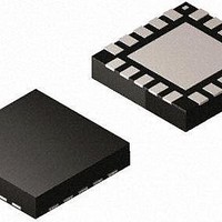
MAX2042ETP+ Maxim Integrated Products, MAX2042ETP+ Datasheet - Page 4

MAX2042ETP+
Manufacturer Part Number
MAX2042ETP+
Description
RF Mixer HI-LIN 2000-3000MHZ W/LO BUFFER
Manufacturer
Maxim Integrated Products
Datasheet
1.MAX2042ETP.pdf
(27 pages)
Specifications of MAX2042ETP+
Frequency Range
1800 MHz to 3000 MHz
Maximum Conversation Loss
7.2 dB
Maximum Operating Frequency
3000 MHz
Maximum Operating Temperature
+ 85 C
Maximum Power Dissipation
5 W
Minimum Operating Temperature
- 40 C
Mounting Style
SMD/SMT
Operating Supply Voltage
5 V
Supply Current
138 mA
Package / Case
TQFN-20
Noise Figure
7.3 dB
Rf Type
General Purpose
Supply Voltage Range
3V To 5.25V
Rf Ic Case Style
QFN
No. Of Pins
20
Operating Temperature Range
-40°C To +85°C
Peak Reflow Compatible (260 C)
Yes
Rohs Compliant
Yes
Leaded Process Compatible
Yes
Lead Free Status / RoHS Status
Lead free / RoHS Compliant
SiGe High-Linearity, 2000MHz to 3000MHz
Upconversion/Downconversion Mixer with LO Buffer
+5.0V SUPPLY AC ELECTRICAL CHARACTERISTICS
(DOWNCONVERTER OPERATION) (continued)
(Typical Application Circuit with tuning elements outlined in Table 1, V
sources, P
T
f
+3.3V SUPPLY AC ELECTRICAL CHARACTERISTICS
(DOWNCONVERTER OPERATION)
(Typical Application Circuit with tuning elements outlined in Table 1, RF and LO ports are driven from 50I sources. Typical values
are for T
noted.) (Note 7)
4
IF
IF Output Impedance
IF Output Return Loss
RF-to-IF Isolation
LO Leakage at RF Port
2LO Leakage at RF Port
LO Leakage at IF Port
Small-Signal Conversion Loss
Loss Variation vs. Frequency
Conversion Loss Temperature
Coefficient
Single Sideband Noise Figure
Noise Figure Temperature
Coefficient
Input 1dB Compression Point
Third-Order Input Intercept Point
IIP3 Variation with T
2RF - 2LO Spur Rejection
3RF - 3LO Spur Rejection
C
= 300MHz. All parameters are guaranteed by design and characterization, unless otherwise noted.) (Note 7)
= -40NC to +85NC. Typical values are for T
______________________________________________________________________________________
C
PARAMETER
LO
= +25NC, V
PARAMETER
= -3dBm to +3dBm, P
C
CC
= +3.3V, P
RF
SYMBOL
SYMBOL
RF
NF
= 0dBm, f
IP
TC
TC
RL
2 x 2
3 x 3
DL
IIP3
Z
L
= 0dBm, P
1dB
IF
SSB
C
CL
NF
IF
C
C
= +25NC, V
RF
Nominal differential impedance at the IC’s
IF outputs
RF terminated into 50I, LO driven by
50I source, IF transformed to 50I using
external components shown in the Typical
Application Circuit
P
f
P
P
f
P
(Note 8)
f
band
T
No blockers present
Single sideband, no blockers present,
T
(Note 10)
f
P
f
P
T
P
P
P
P
LO
LO
RF
RF1
RF1
LO
LO
LO
LO
C
C
RF1
RF1
C
RF
RF
RF
RF
LO
= 2300MHz to 2900MHz, f
= -40NC to +85NC
= -40NC to +85NC
= -40NC to +85NC
= 2300MHz to 2900MHz, any 100MHz
= 2000MHz to 2800MHz,
= 2000MHz to 2800MHz,
= -10dBm, f
= 0dBm, f
= -10dBm, f
= 0dBm, f
= +3dBm (Note 8)
= +3dBm (Note 8)
= +3dBm
= +3dBm (Note 8)
= 2600MHz, f
= 2600MHz, f
= P
= P
= 0dBm, f
RF2
RF2
CC
= +5.0V, P
= 0dBm/tone
= 0dBm/tone,
SPUR
SPUR
CONDITIONS
CONDITIONS
SPUR
SPUR
RF
RF2
RF2
= 2600MHz, f
= f
= f
CC
= f
= f
= 2601MHz,
= 2601MHz,
LO
LO
RF
= +4.75V to +5.25V, RF and LO ports are driven from 50I
LO
LO
+ 150MHz
+ 100MHz
= 0dBm, P
+ 150MHz
+ 100MHz
IF
= 300MHz, f
LO
LO
= 2300MHz, f
= 0dBm, f
LO
MIN
MIN
= 2000MHz to 2600MHz, f
30
RF
IF
= 2300MHz, f
= 300MHz, unless otherwise
Q0.25
0.008
0.019
-24.2
TYP
TYP
-28
-36
7.2
0.2
7.5
50
18
37
20
31
72
62
87
67
MAX
MAX
-22
-16
LO
= 2300MHz,
RF
UNITS
UNITS
dB/NC
dB/NC
dBm
dBm
dBm
dBm
dBm
dBc
dBc
dB
dB
dB
dB
dB
dB
I
> f
LO
,


