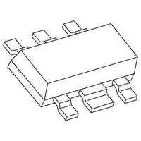
CMY210 TriQuint, CMY210 Datasheet - Page 3

CMY210
Manufacturer Part Number
CMY210
Description
RF Mixer Mixer /Receiver MMIC
Manufacturer
TriQuint
Datasheet
1.CMY210.pdf
(9 pages)
Specifications of CMY210
Frequency Range
500 MHz to 2.5 GHz
Maximum Conversation Loss
7 dB
Maximum Operating Frequency
2.5 GHz
Mounting Style
SMD/SMT
Operating Supply Voltage
3 V
Supply Current
6 mA
Package / Case
MW-6
Noise Figure
6 dB
Lead Free Status / RoHS Status
Lead free / RoHS Compliant
Other names
1014493
Available stocks
Company
Part Number
Manufacturer
Quantity
Price
Company:
Part Number:
CMY210
Manufacturer:
SIEMENS
Quantity:
5 321
Company:
Part Number:
CMY210
Manufacturer:
TriQuint
Quantity:
5 561
Company:
Part Number:
CMY210 E6327
Manufacturer:
RICHTEK
Quantity:
36 000
Part Number:
CMY210 E6327
Manufacturer:
TQ/INFINEON
Quantity:
20 000
Company:
Part Number:
CMY210 E6372
Manufacturer:
TRIQUINT
Quantity:
3 354
CMY 210 Datasheet
________________________________________________________________________________________________________
Electrical Characteristics
Test conditions: T
f
Parameter, Test Conditions
Operating Current
Conversion Loss
SSB Noise Figure
2 Tone 3rd Order IMD
P
f
3rd Order Input Intercept Point
P
LO Leakage at RF/IF-Port (1,6)
Applications Information
Test circuit / application example
LOin
Lumped element values for 800MHz test and application circuit:
For additional information and latest specifications, see our website:
Revision E, September 12, 2006
LO
RF1
RF1
-1dB
MHz
f LO
965
= 965MHz; P
= 806MHz; f
= P
Input Power
C3
in/ out
50 Ohm
RF2
RF
F RF
MHz
808
L3
= -3dBm
3
LO
RF2
CMY210
MHz
F IF
157
L1
= 0dBm; f
a
= 810MHz; f
= 25°C; V
C4
C1
4
8.2
nH
L1
1
L4
Vdd
2,5
IF
= 157MHz, unless otherwise specified:
DD
6
LO
= 3V, see test circuit; f
3.9
C1
pF
=965MHz
L2
C2
8.2
nH
L2
I
L
F
d
Symbol
IP3
P
P
op
c
IM3
ssb
-1dB
LO 1,6
out/ in
50 Ohm
in
3.3
IF
C2
pF
www.triquint.com
Notes for external elements:
L1, C1: Filter for upper frequency;
C2, L2: Filter for lower frequency;
each filter is a throughpath for the
desired frequency (RF or IF) and
isolates the other frequency (IF or
RF) and its harmonics.
These two filters must be
connected to pin 1 and pin 6
directly.
Parasitic capacitances at the ports
1 and 6 must be as small as
possible.
L4 and C4 are optimized by
indicating lowest I
frequency; same procedure for L3.
The ports 1, 3 and 6 must be DC
open.
RF
6.8
nH
min
L3
20
= 808MHz;
-
-
-
-
-
-
C3
pF
47
typ
6.0
5.7
6.0
54
24
14
-8
op
at used LO-
nH
L4
15
max
8.0
7.0
-
-
-
-
-
C4
pF
33
dBm
dBm
dBm
Unit
dBc
mA
dB
dB
4


