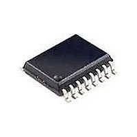
RE46C190S16F Microchip Technology, RE46C190S16F Datasheet - Page 13

RE46C190S16F
Manufacturer Part Number
RE46C190S16F
Description
MOSFET & Power Driver ICs 3V E-Cal Photo S.D. IC
Manufacturer
Microchip Technology
Type
CMOS Photoelectric Smoke Detector ASIC with Interconnect and Timer Moder
Datasheet
1.RE46C190S16F.pdf
(42 pages)
Specifications of RE46C190S16F
Product
Driver ICs - Various
Supply Voltage (max)
5 V
Supply Voltage (min)
2 V
Supply Current
1 uA
Maximum Operating Temperature
+ 60 C
Mounting Style
SMD/SMT
Minimum Operating Temperature
- 10 C
Output Current
- 4 mA
Output Voltage
8.5 V
Package / Case
SOIC-16
Input Voltage
5V
Ic Output Type
Open Drain
Sensor Case Style
SOIC
No. Of Pins
16
Supply Voltage Range
2V To 5V
Lead Free Status / RoHS Status
Lead free / RoHS Compliant
Available stocks
Company
Part Number
Manufacturer
Quantity
Price
Company:
Part Number:
RE46C190S16F
Manufacturer:
MCP
Quantity:
50
Company:
Part Number:
RE46C190S16F
Manufacturer:
MICROCHIP
Quantity:
12 000
3.0
3.1
The internal oscillator is trimmed to ±6% tolerance.
Once every 10 seconds, the boost converter is
powered up, the IRcap is charged from V
the detection circuitry is active for 10 ms. Prior to
completion of the 10 mS period, the IRED pulse is
active for a user-programmable duration of 100-
400 µs. During this IRED pulse, the photo diode current
is integrated and then digitized. The result is compared
to a limit value stored in EEPROM during calibration to
determine the photo chamber status. If a smoke
condition is present, the period to the next detection
decreases, and additional checks are made.
3.2
The digitized photo amplifier integrator output is
compared to the stored limit value at the conclusion of
the IRED pulse period. The IRED drive is all internal,
and
programmable. Three consecutive smoke detections
will cause the device to go into Alarm and activate the
horn and interconnect circuits. In Alarm, the horn is
driven at the high boost voltage level, which is
regulated based on an internal voltage reference, and
therefore results in consistent audibility over battery
life. RLED will turn on for 10 ms at a 2 Hz rate. In Local
Alarm, the integration limit is internally decreased to
provide alarm hysteresis. The integrator has three
separate gain settings:
• Normal and Hysteresis
• Reduced Sensitivity (HUSH)
• High Gain for Chamber Test and Push-to-Test
There are four separate sets of integration limits (all
user programmable):
• Normal Detection
• Hysteresis
• HUSH
• Chamber Test and Push-to-Test modes
In addition, there are user selectable integrator gain
settings to optimize detection levels (see
2010 Microchip Technology Inc.
both
DEVICE DESCRIPTION
Standby Internal Timing
Smoke Detection Circuitry
the
period
and
current
Table
BST
are
and then
4-1).
user
3.3
Once every 86 seconds, the status of the battery
voltage is checked by enabling the boost converter for
10 ms and comparing a fraction of the V
an internal reference. In each period of 344 seconds,
the battery voltage is checked four times. Three checks
are unloaded and one check is performed with the
RLED enabled, which provides a battery load. The
High Boost mode is active only for the loaded low
battery test. In addition, once every 43 seconds the
chamber is activated and a High Gain mode and
chamber test limits are internally selected. A check of
the chamber is made by amplifying background
reflections. The Low Boost mode is used for the
chamber test.
If either the low battery test or the chamber test fails,
the horn will pulse on for 10 ms every 43 seconds, and
will continue to pulse until the failing condition passes.
If two consecutive chamber tests fail, the horn will pulse
on three times for 10 ms, separated by 330 ms every
43 seconds. Each of the two supervisory test audible
indicators is separated by approximately 20 seconds.
As an option, a Low Battery Silence mode can be
invoked. If a low battery condition exists, and the TEST
input is driven high, the RLED will turn on. If the TEST
input is held for more than 0.5 second, the unit will
enter
Section 3.4 “Push-to-Test Operation
the TEST input is driven low, the unit enters in Low
Battery Hush mode, and the 10 ms horn pulse is
silenced for 8 hours. The activation of the test button
will also initiate the 9 minute Reduced Sensitivity mode
described in
Mode”. At the end of the 8 hours, the audible indication
will resume if the low battery condition still exists.
3.4
If the TEST input pin is activated (V
detection rate increases to once every 250 ms after
one internal clock cycle. In Push-to-Test, the photo
amplifier High Gain mode is selected, and background
reflections are used to simulate a smoke condition.
After the required three consecutive detections, the
device will go into a Local Alarm condition. When the
TEST input is driven low (V
Normal Gain is selected, after one clock cycle. The
detection rate continues at once every 250 ms until
three consecutive No Smoke conditions are detected.
At this point, the device returns to standby timing. In
addition, after the TEST input goes low, the device
enters the HUSH mode (see
Sensitivity
the
Supervisory Tests
Push-to-Test Operation (PTT)
Mode”).
Push-to-test
Section 3.6 “Reduced Sensitivity
RE46C190
operation
IL
Section 3.6 “Reduced
), the photo amplifier
DS22271A-page 13
IH
described
(PTT)”. After
), the smoke
DD
voltage to
in


