2N7002-T1 Vishay, 2N7002-T1 Datasheet
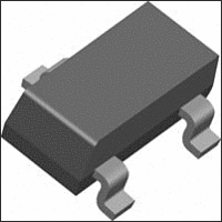
MOSFET Small Signal 60V 0.115A 0.2W

2N7002-T1

Manufacturer Part Number
2N7002-T1
Description
MOSFET Small Signal 60V 0.115A 0.2W
Manufacturer
Vishay
Datasheet

Specifications of 2N7002-T1

Transistor Polarity
N-Channel
Minimum Operating Temperature
- 55 C
Configuration
Single
Resistance Drain-source Rds (on)
7.5 Ohm @ 10 V
Drain-source Breakdown Voltage
60 V
Gate-source Breakdown Voltage
+/- 20 V
Continuous Drain Current
0.115 A
Power Dissipation
200 mW
Maximum Operating Temperature
+ 150 C
Mounting Style
SMD/SMT
Package / Case
SOT-23
Continuous Drain Current Id
115mA
Drain Source Voltage Vds
60V
On Resistance Rds(on)
7.5ohm
Rds(on) Test Voltage Vgs
10V
Threshold Voltage Vgs Typ
2.1V
Lead Free Status / RoHS Status
Lead free / RoHS Compliant
Lead Free Status / RoHS Status
Contains lead / RoHS non-compliant, Lead free / RoHS Compliant

Available stocks

Company
Part Number
Manufacturer
Quantity
Price
Part Number:
2N7002-T1
Manufacturer:
SIEMENS
Quantity:
7
Part Number:
2N7002-T1
Manufacturer:
VISHAY/威世
Quantity:
20 000
Part Number:
2N7002-T1-E3
Manufacturer:
SIX
Quantity:
192 000
Part Number:
2N7002-T1-E3
Manufacturer:
VISHAY
Quantity:
2 959
Part Number:
2N7002-T1-E3
Manufacturer:
VISHAY/威世
Quantity:
20 000
Company:
Part Number:
2N7002-T1-E3
Quantity:
70 000
Part Number:
2N7002-T1-GE3
Manufacturer:
VISHAY
Quantity:
180
Part Number:
2N7002-T1-GE3
Manufacturer:
VISHAY/威世
Quantity:
20 000
Company:
Part Number:
2N7002-T1-GE3
Quantity:
12 000
Document Number: 70226
S-04279—Rev. F, 16-Jul-01
Part Number
D Low On-Resistance: 2.5 W
D Low Threshold: 2.1 V
D Low Input Capacitance: 22 pF
D Fast Switching Speed: 7 ns
D Low Input and Output Leakage
VQ1000P
VQ1000J
2N7000
2N7002
BS170
N
N
NC
G
G
D
S
S
D
1
1
1
2
2
2
V
(BR)DSS
1
2
3
4
5
6
7
G
D
S
Sidebraze: VQ1000P
Plastic: VQ1000J
60
Dual-In-Line
TO-226AA
Min (V)
Top View
Top View
(TO-92)
2N7000
1
2
3
N-Channel 60-V (D-S) MOSFET
r
D Low Offset Voltage
D Low-Voltage Operation
D Easily Driven Without Buffer
D High-Speed Circuits
D Low Error Voltage
DS(on)
7.5 @ V
5.5 @ V
5.5 @ V
5 @ V
5 @ V
14
13
12
11
10
9
8
GS
GS
GS
GS
GS
Max (W)
D
S
G
NC
G
S
D
4
3
= 10 V
= 10 V
4
4
3
3
= 10 V
= 10 V
= 10 V
N
N
V
GS(th)
0.8 to 2.5
0.8 to 2.5
0.8 to 3
1 to 2.5
0.8 to 3
2N7000/2N7002, VQ1000J/P, BS170
(V)
D Direct Logic-Level Interface: TTL/CMOS
D Drivers: Relays, Solenoids, Lamps, Hammers,
D Battery Operated Systems
D Solid-State Relays
I
D
0.115
0.225
0.225
Displays, Memories, Transistors, etc.
0.2
0.5
(A)
G
S
G
D
S
Marking Code: 72wll
72 = Part Number Code for 2N7002
w = Week Code
ll = Lot Traceability
(TO-18 Lead Form)
1
2
TO-92-18RM
(SOT-23)
TO-236
Top View
Top View
BS170
1
2
3
Vishay Siliconix
3
D
www.vishay.com
11-1

Related parts for 2N7002-T1

2N7002-T1 Summary of contents

Page 1

... D Direct Logic-Level Interface: TTL/CMOS D Drivers: Relays, Solenoids, Lamps, Hammers, Displays, Memories, Transistors, etc. D Battery Operated Systems D Solid-State Relays TO-236 (SOT-23 Top View Marking Code: 72wll 72 = Part Number Code for 2N7002 w = Week Code ll = Lot Traceability TO-92-18RM (TO-18 Lead Form Top View BS170 www.vishay.com 11-1 ...

Page 2

... VQ1000J/P, BS170 Vishay Siliconix Parameter Drain-Source Voltage Gate-Source Voltage—Non-Repetitive Gate-Source Voltage—Continuous T = 25_C A Continuous Drain Current Continuous Drain Current (T = 150_C 100_C Pulsed Drain Current T = 25_C A Power Dissipation T = 100_C A Thermal Resistance, Junction-to-Ambient Operating Junction and Storage Temperature Range Notes a. Pulse width limited by maximum junction temperature. ...

Page 3

... Turn-On Time Turn-Off Time Notes a. For DESIGN AID ONLY, not subject to production testing. Pulse test: PW v80 ms duty cycle v1 This parameter not registered with JEDEC. d. Switching time is essentially independent of operating temperature. Document Number: 70226 S-04279—Rev. F, 16-Jul-01 2N7000/2N7002, VQ1000J/P, BS170 _ Symbol Test Conditions ...

Page 4

... VQ1000J/P, BS170 Vishay Siliconix Output Characteristics 1 10 0.8 0.6 0.4 0.2 0 – Drain-to-Source Voltage (V) DS On-Resistance vs. Drain Current 0.0 0.2 0.4 0.6 I – Drain Current (A) D Gate Charge 0 400 800 1200 Q – Total Gate Charge (pC) g www.vishay.com 11 ...

Page 5

... Normalized Effective Transient Thermal Impedance, Junction-to-Ambient (TO-226AA, BS170 Only) 1 Duty Cycle = 0.5 0.2 0.1 0.05 0.1 0.02 0.01 Single Pulse 0.01 0.1 1 Document Number: 70226 S-04279—Rev. F, 16-Jul-01 2N7000/2N7002, VQ1000J/P, BS170 _ = 25_C J 1.0 1.2 1.4 Threshold Voltage 0.50 = 250 0.25 –0.00 –0.25 – ...

Page 6

... Vishay disclaims any and all liability arising out of the use or application of any product described herein or of any information provided herein to the maximum extent permitted by law. The product specifications do not expand or otherwise modify Vishay’ ...

Related keywords