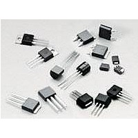
EC103M1 Littelfuse Inc, EC103M1 Datasheet - Page 7

EC103M1
Manufacturer Part Number
EC103M1
Description
SCRs 600V .8A 12uA Sensing
Manufacturer
Littelfuse Inc
Specifications of EC103M1
Breakover Current Ibo Max
20 A
Rated Repetitive Off-state Voltage Vdrm
600 V
Off-state Leakage Current @ Vdrm Idrm
0.002 mA
On-state Rms Current (it Rms)
0.8 A
Forward Voltage Drop
1.7 V
Gate Trigger Voltage (vgt)
0.8 V
Maximum Gate Peak Inverse Voltage
1.2 V
Gate Trigger Current (igt)
12 uA
Holding Current (ih Max)
5 mA
Mounting Style
Through Hole
Package / Case
TO-92
Maximum Operating Temperature
+ 110 C
Minimum Operating Temperature
- 65 C
Configuration
Thyristor
Current Squared Time Rating
1.6
Current, Forward
0.8 A
Current, Reverse
1 μA
Current, Surge
20 A
Package Type
TO-92
Primary Type
SCR
Resistance, Thermal, Junction To Case
75 °C/W
Temperature, Junction, Maximum
+110 °C
Temperature, Operating
-40 to +110 °C
Voltage, Forward
1.7 V
Voltage, Reverse
600 V
Lead Free Status / RoHS Status
Lead free / RoHS Compliant
Data Sheets
Figure E5.4 Maximum Allowable Case Temperature versus
Figure E5.5 Maximum Allowable Ambient Temperature versus
Figure E5.6 Maximum Allowable Ambient Temperature versus
©2004 Littelfuse, Inc.
Thyristor Product Catalog
140
120
100
80
60
40
20
140
120
100
Average On-state Current
On-state Current
RMS On-state Current
80
60
40
20
0
130
120
110
100
0
90
80
70
60
50
40
T106/T107 TO-202
Type 2 and 4
and TO-251
1.5 A and JEDEC
2N Series I
0.1
0
0.2
and EC Series I
TCR22
Devices
RMS On-state Current [I
Average On-state Current [I
0.2
0.4
0.5
T(AV)
On-state Current – Amps
0.3
0.6
T106 and T107
Type 2 and 4
CURRENT WAVEFORM: Sinusoidal
LOAD: Resistive or Inductive
CONDUCTION ANGLE: 180
FREE AIR RATING
0.95
1.0
T(AV)
EC Series I
CURRENT WAVEFORM: Sinusoidal
LOAD: Resistive or Inductive
CONDUCTION ANGLE: 180
CASE TEMPERATURE: Measured
as Shown on Dimensional Drawing
0.8
0.4
CURRENT WAVEFORM: Sinusoidal
LOAD: Resistive or Inductive
CONDUCTION ANGLE: 180
FREE AIR RATING
1.5
1.0
T106/T107 TO-202
Type 1 and 3
T(RMS)
0.5
1.65
T106 and T107
Type 1 and 3
T(RMS)
1.2
1.9
0.6
2.0
T(AV)
1.5 A Devices
and JEDEC
2N Series I
] – Amps
1.4
TO-220
] – Amps
0.7
2.5
2.54
˚
1.6
˚
T(RMS)
0.8
˚
1.8
3.0
0.9
2.0
E5 - 7
Figure E5.7 Maximum Allowable Ambient Temperature versus
Figure E5.8 Maximum Allowable Case Temperature versus
Figure E5.9 Maximum Allowable Case Temperature versus
110
105
100
95
90
85
80
115
110
105
100
95
90
85
80
0
0
140
120
100
Average On-state Current
RMS On-state Current
Average On-state Current
80
60
40
20
6 A TO-220
and TO-202
6 A TO-220
and TO-202
0
1
8 A TO-220
and TO-202
T106/T107 TO-202
Type 2 and 4
and TO-251
8 A TO-220
and TO-202
Average On-state Current [I
2
0.2
Average On-state Current [I
10 A TO-220
and TO-202
10 A TO-220
and TO-202
2
RMS On-state Current [I
0.4
6 A TO-251
and TO-252
4
3
6 A TO-251
and TO-252
CURRENT WAVEFORM: Sinusoidal
LOAD: Resistive or Inductive
CONDUCTION ANGLE: 180
FREE AIR RATING
0.6
4
6
T(AV)
T106/T107 TO-202
Type 1 and 3
0.8
] – Amps
T(RMS)
5
CURRENT WAVEFORM: Sinusoidal
LOAD: Resistive or Inductive
CONDUCTION ANGLE: 180
TEMPERATURE: Measured as
Shown on Dimensional Drawings
CURRENT WAVEFORM: Sinusoidal
LOAD: Resistive or Inductive
CONDUCTION ANGLE: 180
CASE TEMPERATURE: Measured
as Shown on Dimensional Drawings
8 A TO-251
and TO-252
http://www.littelfuse.com
TO-220
T(AV)
] – Amps
8
1.0
6
] – Amps
10 A TO-251
and TO-252
8 A TO-251
and TO-252
+1 972-580-7777
Sensitive SCRs
1.2
˚
10 A TO-251
and TO-252
10
7
˚
˚
1.4


