CDSOD323-T03LC Bourns Inc., CDSOD323-T03LC Datasheet
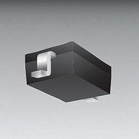
TVS Diodes - Transient Voltage Suppressors Bidirectional Ultra Low Cap

CDSOD323-T03LC

Manufacturer Part Number
CDSOD323-T03LC
Description
TVS Diodes - Transient Voltage Suppressors Bidirectional Ultra Low Cap
Manufacturer
Bourns Inc.
Datasheet

Specifications of CDSOD323-T03LC

Polarity
Bidirectional
Clamping Voltage
7 V
Operating Voltage
3.3 V
Breakdown Voltage
4 V
Termination Style
SMD/SMT
Peak Surge Current
24 A
Peak Pulse Power Dissipation
350 W
Capacitance
0.6 pF
Maximum Operating Temperature
+ 150 C
Minimum Operating Temperature
- 55 C
Dimensions
1.45(Max) mm W x 1.9(Max) mm L
Package / Case
SOD-323
Lead Free Status / RoHS Status
Lead free / RoHS Compliant
Other names
CDS0D323-T03LC

Available stocks

Company
Part Number
Manufacturer
Quantity
Price
Part Number:
CDSOD323-T03LC
Manufacturer:
BOURNS/伯恩斯
Quantity:
20 000
The markets of portable communications, computing and video equipment are
challenging the semiconductor industry to develop increasingly smaller electronic
components.
Bourns offers Transient Voltage Suppressor Diodes for surge and ESD protection
applications in SOD323 package size format. The Transient Voltage Suppressor Diode
series offers a choice of voltage types ranging from 3 V to 24 V in a unidirectional or
bidirectional confi guration.
Bourns
pick and place equipment and their fl at confi guration minimizes roll away. The Bourns
device meets IEC 61000-4-2 (ESD), IEC 61000-4-4 (EFT) and IEC 61000-4-5 (Surge)
requirements.
This device is not recommended for use in VDSL applications.
Notes:
1. Part numbers with suffi x “C” indicate bidirectional device, i.e. CDSOD323-T05LC.
2. For bidirectional devices only, the electrical specifi cations apply in both directions.
3. Unidirectional only: Positive potential is applied from pin 1 to 2.
*No lead detected in standard tests of homogeneous materials.
**RoHS Directive 2002/95/EC Jan 27, 2003 including Annex.
Specifi cations are subject to change without notice.
Customers should verify actual device performance in their specifi c applications.
Parameter
Unidirectional Peak Pulse Power (t
Bidirectional Peak Pulse Power (t
Operating Temperature
Storage Temperature
Minimum ESD Protection (per IEC 61000-4-2)
Parameter
Min. Breakdown Voltage @ 1 mA
Working Peak Voltage
Maximum Clamping Voltage @ I
Typical Clamping Voltage
@ 8/20 µs @ I
Maximum Leakage Current @ V
Typical Capacitance @ 0 V, 1 MHz
General Information
Electrical & Thermal Characteristics (@ T
Contact Discharge
Air Discharge
®
Chip Diodes conform to JEDEC standards, are easy to handle on standard
PP
WM
P
p
= 1 A
p
= 8/20 µs)
= 8/20 µs)
Symbol
A
Features
CDSOD323-TxxLC - TVS Diode Series
V
V
C
V
V
= 25 °C Unless Otherwise Noted)
I
BR
D
M
C
F
P
Lead free as standard*
ESD protection >30 kV
Low capacitance ~ 1.0 pF
Protects 1 line
Uni/bidirectional confi guration
Symbol
T
P
P
ESD
ESD
STG
T
PP
PP
20 V @
L
T03L
Uni-
24 A
4.0
3.3
6.5
5
20 V @
T03LC
24 A
Bi-
4.0
3.3
7.0
5
Asia-Pacifi c: Tel: +886-2 2562-4117 • Fax: +886-2 2562-4116
Europe: Tel: +41-41 768 5555 • Fax: +41-41 768 5510
The Americas: Tel: +1-951 781-5500 • Fax: +1-951 781-5700
www.bourns.com
@ 15 A
18.3 V
T05L
Uni-
6.0
5.0
9.8
5
T05LC
@ 15 A
18.3 V
CDSOD323-
Bi-
6.0
5.0
9.8
5
®
-55 to +150
-55 to +150
1.0
Value
±15
350
250
±8
@ 15 A
18.3 V
Applications
T08L
Uni-
13.4
8.5
8.0
2
HDMI 1.4
Digital Visual Interface (DVI)
USB 3.0 / USB OTG
Memory protection
SIM card ports
UNIDIRECTIONAL
@ 15 A
T08LC
18.3 V
13.4
Bi-
8.5
8.0
2
1
2
@ 11 A
28.6 V
T12L
Uni-
13.3
12.0
19.0
1
BIDIRECTIONAL
T12LC
@ 11 A
28.6 V
13.3
12.0
19.0
Bi-
1
1
2
Unit
ºC
ºC
kV
kV
W
W
Unit
µA
pF
V
V
V
V

Related parts for CDSOD323-T03LC

CDSOD323-T03LC Summary of contents

Page 1

... WM Typical Capacitance @ MHz Notes: 1. Part numbers with suffi x “C” indicate bidirectional device, i.e. CDSOD323-T05LC. 2. For bidirectional devices only, the electrical specifi cations apply in both directions. 3. Unidirectional only: Positive potential is applied from pin *No lead detected in standard tests of homogeneous materials. ...

Page 2

... Maximum Leakage Current @ V WM Typical Capacitance @ MHz Notes: 1. Part numbers with suffi x “C” indicate bidirectional device, i.e. CDSOD323-T05LC. 2. For bidirectional devices only, the electrical specifi cations apply in both directions. 3. Unidirectional only: Positive potential is applied from pin Performance Graphs Peak Pulse Power vs ...

Page 3

... Customers should verify actual device performance in their specifi c applications. Recommended Footprint A H Typical Part Marking Each device has device marking outlined below and the unidirectional devices have an additional Polarity Band indicating the cathode. CDSOD323-T03L ......................................................................... T3 CDSOD323-T03LC ...................................................................... S3 ......... CDSOD323-T05L ......................................................................... T5 CDSOD323-T05LC ....................................................................... S5 CDSOD323-T08L ......................................................................... T8 CDSOD323-T08LC ....................................................................... S8 CDSOD323-T12L ....................................................................... T12 CDSOD323-T12LC .................................................................... S12 CDSOD323-T15L ....................................................................... T15 CDSOD323-T15LC ...

Page 4

... CDSOD323-TxxLC - TVS Diode Series Packaging Information The surface mount product is packaged tape and reel format per EIA-481 standard Index Hole Trailer Device ....... ....... ....... ....... End ....... ....... 10 pitches (min.) Item Symbol Carrier Width A Carrier Length B Carrier Depth C Sprocket Hole d Reel Outside Diameter D Reel Inner Diameter ...

Related keywords