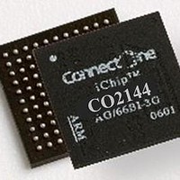
CO2144/48LI-3 Connect One, CO2144/48LI-3 Datasheet - Page 44

CO2144/48LI-3
Manufacturer Part Number
CO2144/48LI-3
Description
Ethernet ICs CO2144 LFBGA FORM FACTOR
Manufacturer
Connect One
Datasheet
1.CO214448LI-3SP.pdf
(63 pages)
Specifications of CO2144/48LI-3
Ethernet Connection Type
10/100 BaseT LAN
Maximum Power Dissipation
200 mW
Minimum Operating Temperature
- 40 C
Mounting Style
SMD/SMT
Product
Ethernet Controllers
Standard Supported
802.11b/g
Data Rate
2.4 Kbps to 3 Mbps
Supply Voltage (max)
3.3 V
Supply Voltage (min)
1.2 V
Maximum Operating Temperature
+ 85 C
Package / Case
LQFP-144
Lead Free Status / RoHS Status
Lead free / RoHS Compliant
Available stocks
Company
Part Number
Manufacturer
Quantity
Price
Company:
Part Number:
CO2144/48LI-3
Manufacturer:
ConnectO
Quantity:
168
Company:
Part Number:
CO2144/48LI-3(SP)
Manufacturer:
ConnectO
Quantity:
8
Connect One
Electrical Specifications
8.3 I/O Line
8.3.1 JTAG Port Pins
TMS, TDI and TCK are Schmitt trigger inputs and are not 5V tolerant. TMS, TDI and TCK do
not integrate a pull-up resistor. TDO is an output, driven at up to VDDIO, and has no pull-up
resistor. The JTAGSEL pin is used only on the prototype. It enables or disables the JTAG
debug functionality.
8.3.2 Reset Pin
The NRST pin is bidirectional with an open drain output buffer. It is handled by the on -chip
reset controller and can be driven low to provide a reset signal to t he external components or
asserted low externally to reset the microcontroller. There is no constraint on the length of the
reset pulse, and the reset controller can guarantee a minimum pulse length. This allows
connection of a simple push-button on the NRST pin as system user reset, and the use of the
signal NRST to reset all the components of the system. The NRST pin integrates a
permanent pull-up resistor to VDDIO.
8.3.3 PIO Controller Lines
All the PIO lines spec to 3.3V with +/- 10% and have an integrated programmable pull-up
resistor. Programming of this pull-up resistor is performed independently for each I/O line
through the PIO controllers. Driving an I/O line with a voltage over VDDIO while the
programmable pull-up resistor is enabled can lead to unpredictable results. Care should be
taken, in particular at reset, as all the I/O lines default to input with pull -up resistor enabled at
reset.
8.3.4 I/O Lines Current Drawing
All the PIO lines can draw up to 8 mA. However, the total current drawn by all the I/O lin es
must not exceed 150 mA.
iChip CO2064/CO2128/CO2144 Data Sheet
8-2


