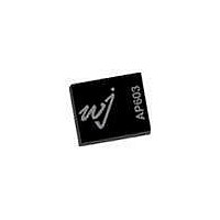
AP603-F TriQuint, AP603-F Datasheet - Page 3

AP603-F
Manufacturer Part Number
AP603-F
Description
RF Amplifier 800-2200MHz 11.8dB Gain
Manufacturer
TriQuint
Type
Power Amplifierr
Datasheet
1.AP603-PCB2140.pdf
(14 pages)
Specifications of AP603-F
Mounting Style
SMD/SMT
Number Of Channels
3
Operating Frequency
2200 MHz
Operating Supply Voltage
28 V
Supply Current
246 mA (Typ) @ 28 V
Maximum Power Dissipation
9500 mW
Maximum Operating Temperature
+ 192 C
Package / Case
DFN-14
Lead Free Status / RoHS Status
Lead free / RoHS Compliant
Other names
1066978
Available stocks
Company
Part Number
Manufacturer
Quantity
Price
Company:
Part Number:
AP603-F
Manufacturer:
M/A-COM
Quantity:
5 000
Part Number:
AP603-F
Manufacturer:
WJ
Quantity:
20 000
WJ Communications, Inc • Phone 1-800-WJ1-4401 • FAX: 408-577-6621 • e-mail: sales@wj.com • Web site: www.wj.com, www.TriQuint.com
The following bias procedure is recommended to ensure proper functionality of AP603 in a laboratory environment. The sequencing is not
required in the final system application.
Turn-on Sequence:
Turn-off Sequence:
Notes:
Application Circuit PC Board Layout
PCB Material: 0.0147” Rogers Ultralam 2000, single layer, 1 oz Cu,
1.
2.
3.
4.
5.
1.
2.
3.
4.
1.
2.
3.
ε
r
= 2.45, Microstrip line details: width = .042”, spacing = .050”
Attach input and output loads onto the evaluation board.
Turn on power supply Vcc = +28V.
Turn on power supply Vbias = +5V. At this point, the only current drawn by the device is leakage current (< 25μA).
Turn on power supply Vpd = +5V. Power supply Vcc should now be drawing typical Icq = 160mA.
Turn on RF power.
Turn off RF power.
Turn off power supply Vpd = +5V.
Turn off power supply Vbias = +5V.
Turn off power supply Vcc = +28V.
Icq can be adjusted with the resistor R2 from the Vpd (+5V) supply and the PIN_VPD (pin14) of the amplifier. Increasing R2
results in a lower Icq. Icq should not be increased above 320mA.
Vpd is used as a reference for the internal active bias circuitry. It can be used to turn on/off the amplifier. Ipd depends on the Icq
quiescent current setting. Ipd can be up to 8mA at a quiescent current setting of 320mA.
Vbias should be maintained fixed at +5V. Ibias will change based on RF input power level. It can be up to 8mA on the AP603.
AP603
High Dynamic Range 7W 28V HBT Amplifier
8
6
4
2
0
0
Evaluation Board Bias Procedure
100
Icq Setting (mA)
Ipd vs Icq
200
300
Vbias
Bias.
Vpd
Vcc
400
Notes:
1. Please note that for reliable operation, the evaluation board will have to be mounted to a much larger
2. The area around the module underneath the PCB should not contain any soldermask in order to
3. For proper and safe operation in the laboratory, the power-on sequencing is recommended.
Voltage (V)
heat sink during operation and in laboratory environments to dissipate the power consumed by the
device. The use of a convection fan is also recommended in laboratory environments.
maintain good RF grounding.
8
6
4
2
0
22
+28
+5
+5
Output Average Power (dBm)
Ibias vs Output Power
24
Baseplate Configuration
26
Specifications and information are subject to change without notice
28
30
32
Page 3 of 14 May 2007 ver 1


