OCB100-KIT Optek, OCB100-KIT Datasheet - Page 12

OCB100-KIT
Manufacturer Part Number
OCB100-KIT
Description
Optical Sensor Development Tools Sensor Design Kit Trans, Reflec, Fluid
Manufacturer
Optek
Datasheet
1.OCB100-KIT.pdf
(24 pages)
Specifications of OCB100-KIT
Description/function
Design Kit
Lead Free Status / RoHS Status
Lead free / RoHS Compliant
Available stocks
Company
Part Number
Manufacturer
Quantity
Price
Company:
Part Number:
OCB100-KIT
Manufacturer:
TT Electronics/Optek Technolog
Quantity:
135
where the green light comes on, a blue LED may come on for some
range of distance. The blue light indicates that V
has risen to
OUT
a level of 2/3 Vcc or greater. You can experiment with calibrating
the sensor at various distances to see how this changes the dis-
tances at which the green and blue LEDs come on. Monitor the
V
voltage directly by connecting a volt meter or an oscilloscope
OUT
between the white and black wires of the mating connector. If you
move the sensor too far or too close to the paper, the circuit will be
unable to calibrate because the V
cannot reach ½ Vcc even when
OUT
the LED has ramped to it’s maximum value allowed by the calibra-
tion circuit (@ 14mA). When this happens, a red LED indicator will
flash multiple times and then remain lit to notify the user that the
circuit could not calibrate. In practice, the OPB732 family LEDs can
12
be driven at DC current levels up to 50mA (maximum rating at room
temperature).
See the device data sheet at www.optekinc.com for more details.
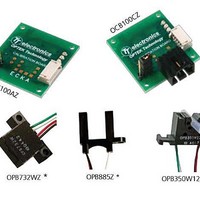
Applicable part numbers: OPB732, OPB732CZ, OPB732WZ
OCB100-KIT


