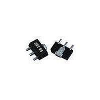
WJA1015-PCB TriQuint, WJA1015-PCB Datasheet - Page 3

WJA1015-PCB
Manufacturer Part Number
WJA1015-PCB
Description
WiFi / 802.11 Modules & Development Tools 50-2300MHz Eval Brd 15dB Gain
Manufacturer
TriQuint
Datasheet
1.WJA1015-PCB.pdf
(4 pages)
Specifications of WJA1015-PCB
Wireless Frequency
50 MHz to 2.3 GHz
Operating Voltage
5 VDC
Operating Temperature Range
- 40 C to + 85 C
For Use With/related Products
WJA1015
Lead Free Status / RoHS Status
Lead free / RoHS Compliant
Other names
1067257
Available stocks
Company
Part Number
Manufacturer
Quantity
Price
Part Number:
WJA1015-PCB
Manufacturer:
WJ
Quantity:
20 000
WJ Communications, Inc • Phone 1-800-WJ1-4401 • FAX: 408-577-6621 • e-mail: sales@wj.com • Web site: www.wj.com, www.TriQuint.com
RF IN
Capacitor
Blocking
C1
S-Parameters (V
WJA1015
+5V Active-Bias InGaP HBT Gain Block
Freq
1000
1100
1200
1300
1400
1500
1600
1700
1800
1900
2000
2100
2200
2300
2400
100
200
300
400
500
600
700
800
900
10
50
0 Ω
R1
device
WJA1015
S11 (dB)
-10.52
-13.48
-13.75
-13.81
-13.66
-13.63
-13.47
-13.31
-13.34
-13.32
-13.51
-13.67
-13.80
-14.10
-14.21
-14.27
-14.40
-14.59
-14.70
-15.08
-15.61
-16.45
-17.56
-18.91
-20.49
-21.25
= +5 V, I
RF Choke
Device S-parameters are available for Download from the website at: http://www.wj.com
0 Ω
Vcc =+5.00V
R4
Icc = 65 mA
Recommended Component Values
1.
2.
3.
L1
CC
Ref. Name
L1
C1, C2
C3
R1, R2, R4
C4, C5, C6,
R3, R5, R6,
R7, R8
S11 (ang)
= 65 mA, T = 25 °C, calibrated to device leads)
Capacitor
The listed values are contained on the evaluation board to achieve optimal broadband performance
For lower cost and performance (500 – 2000 MHz) option use 39 nH air core wire wound inductor.
Place holders for the 0Ω resistors and “Do Not Place” references are not needed for final design.
-143.67
-161.89
-172.53
-176.48
-178.58
-179.99
-178.57
-177.69
-175.45
-174.25
-169.52
-166.20
-162.14
-158.81
-155.59
-153.43
-151.37
-150.40
-150.57
-150.87
-152.92
-154.54
-160.54
-168.57
-177.69
Bypass
-63.44
C3
0 Ω
R2
Capacitor
Blocking
Value / Type
470 nH ferrite core wire wound inductor
1000 pF NPO chip capacitor
0.018 μF chip capacitor
0 Ω
Do Not Place
Typical Device Data
S21 (dB)
C2
Application Circuit
19.18
15.63
15.19
15.00
14.98
15.01
14.95
14.96
14.95
14.90
14.86
14.90
14.80
14.80
14.80
14.69
14.71
14.65
14.64
14.59
14.57
14.53
14.47
14.35
14.14
14.03
(3)
RF OUT
S21 (ang)
(3)
163.04
165.20
167.85
164.59
159.98
154.44
148.76
142.99
136.98
131.21
125.45
119.75
113.81
107.10
101.11
95.41
89.04
82.49
76.20
69.52
63.11
56.88
50.44
43.55
37.00
30.16
(1)
S12 (dB)
-22.14
-19.24
-19.06
-18.97
-18.98
-18.98
-18.94
-19.03
-19.00
-18.98
-18.93
-19.04
-18.92
-19.06
-18.97
-18.95
-18.99
-18.98
-18.91
-18.98
-18.98
-19.05
-19.04
-19.07
-19.15
-19.21
Specifications and information are subject to change without notice
S12 (ang)
(2)
-10.20
-13.34
-14.96
-18.27
-20.07
-23.10
-25.79
-27.81
-30.44
-32.99
-35.65
-38.51
-40.77
-42.85
-46.28
-48.85
-52.12
-54.41
-57.85
-60.45
24.30
-2.21
-5.58
-8.03
6.82
1.99
Size
0805
0603
0603
0603
S22 (dB)
-15.61
-18.12
-19.28
-19.52
-19.74
-19.63
-19.65
-19.11
-19.08
-18.25
-17.45
-16.68
-15.96
-15.20
-14.76
-14.17
-13.96
-13.52
-13.26
-12.73
-12.16
-11.65
-10.86
-10.32
-7.41
-9.48
S22 (ang)
-110.90
-135.80
-152.96
-158.45
-161.23
-162.42
-165.00
-162.52
-163.06
-160.28
-160.15
-157.71
-158.14
-157.24
-157.30
-158.38
-158.75
-159.89
-161.07
-163.72
-164.41
-167.15
-170.33
-173.23
-176.01
-45.95
Page 3 of 4
July 2008


