TWR-WIFI-RS2101 Freescale Semiconductor, TWR-WIFI-RS2101 Datasheet - Page 5
TWR-WIFI-RS2101
Manufacturer Part Number
TWR-WIFI-RS2101
Description
WiFi / 802.11 Modules & Development Tools Tower WIFI Module
Manufacturer
Freescale Semiconductor
Datasheet
1.TWR-WIFI-RS2101.pdf
(9 pages)
Specifications of TWR-WIFI-RS2101
Interface Type
SPI
Modulation
802.11b/g/n
Security
WEP, WPA, WPA2
Operating Voltage
3.1 V to 3.6 V
Antenna
Integrated
For Use With/related Products
RS2101
Lead Free Status / RoHS Status
Lead free / RoHS Compliant


3.2 System Power
The RS9110‐N‐11‐21 is powered from a source in an assembled Tower System via the 3.3V supply on
the Primary Elevator Connector.
3.3 Access Header
The SPI and interrupt signals are routed to both the Primary Elevator connector and a 2x5 pin header.
This Access Header can be used to access the RS9110‐N‐11‐21 module signals for probing or for use
outside of the Tower System. The pinout is shown in Table 1.
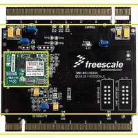
3.4 Elevator Connections
The TWR‐WIFI‐RS2101 features two expansion card‐edge connectors that interface to Elevator boards
in a Tower system: the Primary and Secondary Elevator connectors. The Primary Elevator connector,
comprised of sides A and B, is utilized by the TWR‐WIFI‐RS2101, while the Secondary Elevator
connector only makes connections to ground (GND). Table 2 provides the pinout for the Primary
Freescale MCU
MQX OS/TCP IP
Applications
SLIP
RS9110‐N‐11‐21
3.3V
Supply
Reset
SPI_DATAOUT
Figure 2. RS9110‐N‐11‐21 Module: Functional Block Diagram
SPI
Signal
SPI_DATAIN
No Connect
Table 1. Access Header Connections
SPI_CLK
TWR‐WIFI‐RS2101 User’s Manual
3.3V
1
3
5
7
9
WLAN St ack
RS9110
Pin
SLIP
Reset
10
2
4
6
8
RS9110-N-11-21-01
GND
SPI_INTR
No Connect
SPI_CS
GND
GPIO
RS9110 WLAN Subsystem
RS9110‐N‐11‐21
Transceiver
Flash
XO
SPI/UART
Selection
Signal
RF
LED
BT Coexistence I/f
RF
FE
Test Port
Page 5 of 9
Related parts for TWR-WIFI-RS2101
Image
Part Number
Description
Manufacturer
Datasheet
Request
R

Part Number:
Description:
MCU, MPU & DSP Development Tools TOWER WIFI MOD-GAIN SPAN
Manufacturer:
Freescale Semiconductor
Datasheet:

Part Number:
Description:
TOWER SYSTEM WIFI MODULE
Manufacturer:
Freescale Semiconductor
Part Number:
Description:
WiFi / 802.11 Development Tools TOWER RF MODULE FOR MRB
Manufacturer:
Freescale Semiconductor
Datasheet:

Part Number:
Description:
TOWER SYSTEM ZGWIFI
Manufacturer:
Freescale Semiconductor
Datasheet:

Part Number:
Description:
Manufacturer:
Freescale Semiconductor, Inc
Datasheet:
Part Number:
Description:
Manufacturer:
Freescale Semiconductor, Inc
Datasheet:
Part Number:
Description:
Manufacturer:
Freescale Semiconductor, Inc
Datasheet:
Part Number:
Description:
Manufacturer:
Freescale Semiconductor, Inc
Datasheet:
Part Number:
Description:
Manufacturer:
Freescale Semiconductor, Inc
Datasheet:
Part Number:
Description:
Manufacturer:
Freescale Semiconductor, Inc
Datasheet:
Part Number:
Description:
Manufacturer:
Freescale Semiconductor, Inc
Datasheet:
Part Number:
Description:
Manufacturer:
Freescale Semiconductor, Inc
Datasheet:
Part Number:
Description:
Manufacturer:
Freescale Semiconductor, Inc
Datasheet:
Part Number:
Description:
Manufacturer:
Freescale Semiconductor, Inc
Datasheet:
Part Number:
Description:
Manufacturer:
Freescale Semiconductor, Inc
Datasheet: