MDEV-418-HH-KF3-MS Linx Technologies Inc, MDEV-418-HH-KF3-MS Datasheet - Page 4
MDEV-418-HH-KF3-MS
Manufacturer Part Number
MDEV-418-HH-KF3-MS
Description
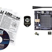
RF Modules & Development Tools 3 Button MS Keyfob Dev Sys 418MHz
Manufacturer
Linx Technologies Inc
Datasheet
1.MDEV-418-HH-KF5-MS.pdf
(7 pages)
Specifications of MDEV-418-HH-KF3-MS
Supply Voltage (min)
7 V
Product
RF Modules
Maximum Frequency
418 MHz
Supply Voltage (max)
16 V
Supply Current
500 mA
Lead Free Status / RoHS Status
Lead free / RoHS Compliant


THE DECODER BOARD (CONT.)
Page 6
Figure 5: The Decoder Area
The Decoder Area
The figure below shows the decoder area of the development board.
The decoder is in the center beneath the Linx logo. To the left are LEDs that are
connected to the decoder data lines. These will light up when the decoder
receives a signal from the transmitter instructing it to take the data line high. LED
D0 corresponds to data line D0 and so forth.
Beneath the decoder are two LEDs. D12 is connected to the MODE_IND line.
D8 is connected to the RX_CNTL line and will provide visual feedback by lighting
up when the decoder activates the receiver when in RX Control Mode.
Under the LEDs is a button that is connected to the LEARN line. This button is
used to learn the Code Word from the encoder as described in the MS Series
Decoder Data Guide.
There are four switches to the left of the CREATE / LEARN button. BSEL0 and
BSEL1 are used to set the baud rate of the decoder as shown in the chart below.
The Keyfob transmitter is set to 9,600bps, so BSEL0 should be on and BSEL1
should be off. If the switch is up,
then the line is high (on); if down,
then the line is low (off).
*Important* The decoder board must be
set to the same baud rate as the
transmitter in order for the signal to be
received correctly.
The PDN switch will connect the RX_CNTL line of the encoder to the PDN line
of the receiver so that the RX Control Mode can be tested. This mode is
described in the MS Series Decoder Data Guide.
The LATCH switch will place the decoder into Latch Mode when on, so that the
data lines will go high when a valid signal is received and stay high until a second
valid signal is received. If the switch is off, the data lines are momentary.
BSEL1
0
0
1
1
BSEL0
0
1
0
1
Baud Rate
19,200
28,800
2,400
9,600
THE DECODER BOARD (CONT.)
Figure 6: The Decoder Board USB Area
The USB Area
The decoder board has a Linx SDM-USB-QS-S USB module for use with the
included development software. This module is powered by the USB bus, so it
will not pull any current from the battery. The figure below shows this section.
The microcontroller on the right monitors the data lines and generates
commands that are sent to the development software on the PC via the QS
Series USB module. The RX_IND LED to the left of the module will flash to
indicate that data is being received from the PC, and the TX_IND line will flash
to indicate that the module is sending data to the PC.
The QS Series USB module provides a simple serial link to a PC via a USB
connection. It converts logic-level serial signals to USB-compliant signals and
vice versa, so it can be connected to virtually any serial device, including
microcontrollers, RS-232 / RS-485 level converters, or Linx RF modules. It is
completely self-contained, requiring only a USB type B jack, and includes all
necessary firmware and drivers.
Page 7
Related parts for MDEV-418-HH-KF3-MS
Image
Part Number
Description
Manufacturer
Datasheet
Request
R

Part Number:
Description:
KIT MASTER DEV MS KEYFOB 418MHZ
Manufacturer:
Linx Technologies Inc
Datasheet:

Part Number:
Description:
KIT DEV MS HANDHELD TX 418MHZ
Manufacturer:
Linx Technologies Inc
Datasheet:

Part Number:
Description:
KIT DEV TX 418MHZ HS COMPACT
Manufacturer:
Linx Technologies Inc
Datasheet:

Part Number:
Description:
KIT DEV TX 418MHZ MS SERIES
Manufacturer:
Linx Technologies Inc
Datasheet:

Part Number:
Description:
KIT DEV TX 418MHZ HS LONG-RANGE
Manufacturer:
Linx Technologies Inc
Datasheet:

Part Number:
Description:
RF Modules & Development Tools 1 Button MS Keyfob Dev Sys 418MHz
Manufacturer:
Linx Technologies Inc
Datasheet:
Part Number:
Description:
RF Modules & Development Tools 4 Button MS Keyfob Dev Sys 418MHz
Manufacturer:
Linx Technologies Inc
Datasheet:
Part Number:
Description:
RF Modules & Development Tools 2 Button MS Keyfob Dev Sys 418MHz
Manufacturer:
Linx Technologies Inc
Datasheet:

Part Number:
Description:
RF Development Tools 1-5 Button Keyfob Dev Sys 418MHz
Manufacturer:
Linx Technologies
Datasheet:

Part Number:
Description:
HOLDER BATTERY 20MM COIN CR2032
Manufacturer:
Linx Technologies Inc
Datasheet:

Part Number:
Description:
MODULE USB LOW SPEED
Manufacturer:
Linx Technologies Inc
Datasheet:

Part Number:
Description:
IC TRANSCODER MT BI-DIR 20-SSOP
Manufacturer:
Linx Technologies Inc
Datasheet:

Part Number:
Description:
IC ENCODER LOW SECURITY 8DIP
Manufacturer:
Linx Technologies Inc
Datasheet:

Part Number:
Description:
IC DECODER MS SERIES 20-SSOP
Manufacturer:
Linx Technologies Inc
Datasheet:
Part Number:
Description:
IC ENCODER MS SERIES 20-SSOP
Manufacturer:
Linx Technologies Inc
Datasheet: