XDM2510HP RFM, XDM2510HP Datasheet - Page 10
XDM2510HP
Manufacturer Part Number
XDM2510HP
Description
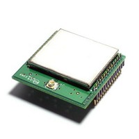
RF Modules & Development Tools 2.4 GHz WirelessHART Pin Version
Manufacturer
RFM
Datasheet
1.XDM2510HP.pdf
(16 pages)
Specifications of XDM2510HP
Board Size
1.05 in x 0.985 in
Minimum Frequency
2.4 GHz
Minimum Operating Temperature
- 40 C
Supply Voltage (min)
3.3 V
Product
RF Modules
Maximum Frequency
2.4835 GHz
Output Power
8 dBm
Antenna
U.FL Connector
Supply Voltage (max)
5.5 V
Supply Current
18 mA
Maximum Operating Temperature
+ 85 C
Lead Free Status / RoHS Status
Lead free / RoHS Compliant


7.0 Boot Sequence
Following the active low assertion of /RESET IN, the XDM2510H completes its boot-up process by loading and
decrypting the application image and loading the operating parameters. During the boot process, the modules
output signals are not actively driven and the input signals are ignored. The duration of the boot process is de-
fined in Table 10.
8.0 Hardware Interfaces
8.1 /RESET IN
When this signal is asserted low, the XDM2510H is hardware reset until the signal is de-asserted. Note that the
XDM2510H may also be reset using the reset serial command. If a system is designed to assert /RESET IN after
the XDM2510H has completed its boot process, it is recommended the module be placed into deep sleep prior to
assertion of the /RESET IN signal.
8.2 /TIME
The XDM2510H has the ability to deliver network-wide synchronized timestamps. The XDM2510H sends a time
packet through its serial interface when one of the following occurs:
Use of the /TIME input is optional but has the advantage of being more accurate. The value of the timestamp is
taken within approximately 1 ms of receiving a /TIME signal assertion. The XDM2510H will send the time packet
to the local host microcontroller within 100 ms of the strobe. If the HDLC request is used, due to packet process-
ing the value of the timestamp may be captured several milliseconds after receipt of the packet. The real time de-
livered to the sensor processor is relative to the real-time clock on the Network Manager, which serves as the
Network Real Time Clock (NRTC).
www.RFM.com
©2010-2011 by RF Monolithics, Inc.
•
•
t
boot_delay
Boot Parameter
HDLC request for time is received.
Active-low /TIME signal is asserted.
E-mail:
info@rfm.com
Minimum
TIME
TX
t
strobe
Typical
Technical support +1.800.704.6079
t
response
E-mail: tech_sup@rfm.com
Table 11
Figure 3
Figure 4
Maximum
6
Time Packet
Units
s
The time between power up and
serial interface availability
Comments
XDM2510H - 03/17/11
Page 10 of 16
Related parts for XDM2510HP
Image
Part Number
Description
Manufacturer
Datasheet
Request
R

Part Number:
Description:
ASH RX 115.2 KBPS 433.92 MHZ
Manufacturer:
RFM
Datasheet:

Part Number:
Description:
RFIC TRANCEIVER MULTI-CHANNEL FS
Manufacturer:
RFM
Datasheet:

Part Number:
Description:
ASH TX 115.2 KBPS 433.92 MHZ
Manufacturer:
RFM
Datasheet:
Part Number:
Description:
Filters 1602MHz BW=61MHz
Manufacturer:
RFM
Datasheet:

Part Number:
Description:
RESONATOR, SM3030-6
Manufacturer:
RFM
Datasheet:

Part Number:
Description:
RESONATOR, SM3030-6
Manufacturer:
RFM
Datasheet:

Part Number:
Description:
RESONATOR, SM3030-6
Manufacturer:
RFM
Datasheet:

Part Number:
Description:
RESONATOR, SM5035-4
Manufacturer:
RFM
Datasheet:
Part Number:
Description:
RESONATOR 418MHZ SM5035-4
Manufacturer:
RFM
Datasheet:
Part Number:
Description:
RESONATOR 315 MHZ SMD
Manufacturer:
RFM
Datasheet:

Part Number:
Description:
10-Terminal Ceramic Surface-Mount Case 7 x 5 mm Nominal Footprint
Manufacturer:
RFM [RF Monolithics, Inc]
Datasheet:
Part Number:
Description:
QUAD-BAND GSM850/GSM/DCS/PCS POWER AMP MODULE
Manufacturer:
RFM [RF Monolithics, Inc]
Datasheet:
Part Number:
Description:
402 to 405 MHz Medical Band Front-end Filter
Manufacturer:
RFM [RF Monolithics, Inc]
Datasheet:
Part Number:
Description:
674.03 MHz SAW Resonator
Manufacturer:
RFM [RF Monolithics, Inc]
Datasheet: