EBWT11-A Bluegiga Technologies, EBWT11-A Datasheet - Page 10
EBWT11-A
Manufacturer Part Number
EBWT11-A
Description
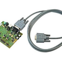
Bluetooth / 802.15.1 Modules & Development Tools WT11 Eval Board with WT11-A Mod iWRAP 3.0
Manufacturer
Bluegiga Technologies
Specifications of EBWT11-A
Interface Type
RS-232, USB, SPI, UART
Data Rate
3 Mbps
Operating Voltage
3.3 V
Operating Temperature Range
- 40 C to + 85 C
Output Power
15 dBm
Technology/ Type
Evaluation Board
Silicon Manufacturer
Bluegiga
Application Sub Type
Bluetooth
Kit Application Type
Wireless Connectivity
Silicon Core Number
WT11
Lead Free Status / RoHS Status
Lead free / RoHS Compliant
For Use With/related Products
WT11-A
Lead Free Status / Rohs Status
Lead free / RoHS Compliant


8. PIO SELECT (J3)
This switch toggles PIO2 to PIO7 signal connections between J2 connector and
LED/USB/UART interfaces.
Note: ‘Top’ and ‘bottom’ positions refer to viewing WT11 Evaluation Kit from top side as
seen in Figure 2.
J3 Switch top position:
J3 Switch bottom position:
9. RESET (J4)
The RESET button resets the module using the reset pin on the WT11.
10. DSR (J5)
The DSR button is connected to PIO5 pin on the WT11. Thus, when you want to use the
DSR signal, please refer to the iWRAP 2.1.0 manual. The use of DSR signal is described
under SET CONTROL ESCAPE chapter.
11. SPEAKER JACK (J6)
Connect your generic PC headset’s 3,5mm speaker plug here.
12. MICROPHONE JACK (J7)
Connect your generic PC headset’s 3,5mm headphone plug here.
•
•
•
•
•
•
•
•
•
•
•
•
•
•
Top position must be used when WT11 module is interfaced trough J2 connector.
Bottom position is used when WT11 module is interfaced trough the DB9 RS232
connector or if USB port or if link state LED is used.
PIO2 connects to pin 3 on the J2 interface
PIO3 connects to pin 4 on the J2 interface
PIO4 connects to pin 5 on the J2 interface
PIO5 connects to pin 6 on the J2 interface
PIO6 connects to pin 7 on the J2 interface
PIO7 connects to pin 8 on the J2 interface
PIO2 connects to USB_IO1
PIO3 connects to nDTR-UART
PIO4 connects to nCD-UART
PIO5 connects to nDSR-MUX
PIO6 connects to VBUS
PIO7 connects to blue LED on the board marked with PIO7
9
Related parts for EBWT11-A
Image
Part Number
Description
Manufacturer
Datasheet
Request
R

Part Number:
Description:
Bluetooth / 802.15.1 Modules & Development Tools WT11 Eval Brd
Manufacturer:
Bluegiga Technologies
Datasheet:

Part Number:
Description:
Bluetooth / 802.15.1 Modules & Development Tools WT11-A Evl Brd w/HDP firmwr w/IEEE Agents
Manufacturer:
Bluegiga Technologies

Part Number:
Description:
Bluetooth / 802.15.1 Modules & Development Tools Access Point 7 Connections
Manufacturer:
Bluegiga Technologies

Part Number:
Description:
Bluetooth / 802.15.1 Modules & Development Tools Access Server 14 Connections
Manufacturer:
Bluegiga Technologies
Datasheet:

Part Number:
Description:
Bluetooth / 802.15.1 Modules & Development Tools WT32 Evaluation Kit
Manufacturer:
Bluegiga Technologies
Datasheet:

Part Number:
Description:
Bluetooth / 802.15.1 Modules & Development Tools WT12 Eval Board with WT12 Mod, iWRAP 3.0
Manufacturer:
Bluegiga Technologies
Datasheet:

Part Number:
Description:
Bluetooth / 802.15.1 Modules & Development Tools Access Server 7 Connections
Manufacturer:
Bluegiga Technologies
Datasheet:

Part Number:
Description:
Bluetooth / 802.15.1 Modules & Development Tools WT21 HCI Modulem No Ant
Manufacturer:
Bluegiga Technologies
Datasheet:
Part Number:
Description:
Bluetooth / 802.15.1 Modules & Development Tools Access Point 7 Con External Antenna
Manufacturer:
Bluegiga Technologies

Part Number:
Description:
Bluetooth / 802.15.1 Modules & Development Tools WT41 Eval Brd
Manufacturer:
Bluegiga Technologies
Datasheet:

Part Number:
Description:
Bluetooth / 802.15.1 Modules WT32 Audio Mod w/ Chip Ant iWRAP 5.0
Manufacturer:
Bluegiga Technologies
Part Number:
Description:
Bluetooth / 802.15.1 Modules WT12 Class 2 2.1+EDR w/Chip Ant iWRAP 5.0
Manufacturer:
Bluegiga Technologies
Part Number:
Description:
Bluetooth / 802.15.1 Modules WT11i Class1 2.1+EDR Chip Ant, iWRAP 2.2
Manufacturer:
Bluegiga Technologies
Datasheet:
Part Number:
Description:
Bluetooth / 802.15.1 Modules WT11i Class1 2.1+EDR Chip Ant, iWRAP 3.0
Manufacturer:
Bluegiga Technologies
Datasheet:
Part Number:
Description:
Bluetooth / 802.15.1 Modules WT11i Class1 2.1+EDR uFL Conn iWRAP 4
Manufacturer:
Bluegiga Technologies
Datasheet: