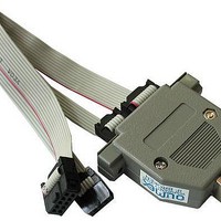
AVR-ISP500 Olimex Ltd., AVR-ISP500 Datasheet - Page 9

AVR-ISP500
Manufacturer Part Number
AVR-ISP500
Description
Programmers & Debuggers USB AVR PROGRAMMER
Manufacturer
Olimex Ltd.
Datasheet
1.AVR-ISP500.pdf
(12 pages)
Specifications of AVR-ISP500
Positions/sockets
1
Description/function
AVR Programmer
Tool Type
Programmer
Core Architecture
AVR
Lead Free Status / RoHS Status
Lead free / RoHS Compliant
For Use With/related Products
AVR Studio
Lead Free Status / Rohs Status
Lead free / RoHS Compliant
FIRMWARE UPGRADE:
TROUBLESHOOTING GUIDE:
This clock output can be really helpful when target AVR is accidentally
programmed with External Clock FUSE option. To resurrect it just wire
ICSP10 pin 3 to XTAL1 pin of the target AVR chip and initiate a
programming session to fix the FUSE values.
AVR-ISP500 contains a built-in boot loader for easy firmware upgrade.
Device enters boot loader mode if the application FLASH section is
corrupted. To force the device to enter boot loader mode for manual
firmware update do the following:
Jumper can now be removed. The device will stay in boot loader mode until
it is power cycled.
Boot loader implements the standard protocol XMODEM with CRC16 for
firmware update. User is free to use his favorite terminal client
(HyperTerminal, minicom, etc) to upload the firmware images taken from
our website. The AVR-ISP500 boot loader implements a USB virtual serial
port that is baud rate agnostic.
As an alternative we provide a simple Windows GUI application for users
who don’t want to or cannot use terminal software.
After the firmware image is uploaded the target will blink the GREEN LED if
update was successful, otherwise it will blink the RED LED if firmware
image was invalid or update was unsuccessful. Device stays in this state
until it is power cycled.
Problem: AVR Studio cannot find my programmer.
Probable causes and solutions:
1. Disconnect the programmer from any power source (external
2. Disconnect the programmer from any target boards.
3. Put a jumper between pin 1 and pin 3 of the ICSP10 connector.
4. Power up the device by connecting it to USB.
5. Device now must be in boot loader mode, indicated by the LED light
AC/DC, USB).
sequence:
Look whether the programmer is listed in Device Manager under the
“Ports (COM & LPT)” section. If it's not there then check your USB
cables and hubs. Reinstall the driver.
Check that the green LED is constantly on.
programmer might be in firmware upgrade mode. Go to the firmware
upgrade section for more details.
Your serial port number might be too high. Check the manual
section “Installing drivers” for more information on assigning serial
port numbers. Also go to AVR Studio menu “Tools->Options” and set
the “Number of COM ports to try” field to at least 20.
Remove all applications that might be using or scanning your
computer's serial ports, including any serial port monitors. They
might mess up the STK500v2 communication between AVR Studio
and the programmer.
a. RED off, GREEN on.
b. RED on, GREEN off.
c. RED off, GREEN off.
If not then the


