AGLP-EVAL-KIT Actel, AGLP-EVAL-KIT Datasheet - Page 42
AGLP-EVAL-KIT
Manufacturer Part Number
AGLP-EVAL-KIT
Description
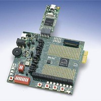
MCU, MPU & DSP Development Tools IGLOO PLUS Starter Kit
Manufacturer
Actel
Datasheet
1.AGLP-EVAL-KIT.pdf
(62 pages)
Specifications of AGLP-EVAL-KIT
Processor To Be Evaluated
CSG289
Interface Type
USB, JTAG
Operating Supply Voltage
1.2 V to 1.5 V
Lead Free Status / RoHS Status
Lead free / RoHS Compliant


Operation of Board Components
Interface Connector
42
A standard interface connector on the board can be used to connect additional daughter cards, some of which are
developed by partners and third party vendors
SRAM memory interfaces, keyboard interfaces for embedded applications, LCD interfaces, and motor control
interfaces. GPIOA_1, GPIOA_2, GPIOA_4, and GPIOA_31 pins can be used for critical signals, such as clock and
reset, because proper series termination has been provided on these signal lines.
{3}
{3}
{3}
{3}
{3}
{3}
{3}
{3}
{3}
{3}
{3}
{3}
{3}
{3}
{3}
{3}
{3}
GPIOA_1
GPIOA_3
GPIOA_5
GPIOA_7
GPIOA_9
GPIOA_13
GPIOA_15
GPIOA_17
GPIOA_19
GPIOA_21
GPIOA_23
GPIOA_25
GPIOA_27
GPIOA_29
GPIOA_31
GPIOA_33
GPIOA_35
Pin No:15 & 16 Should be NC For Matting Connector Polarised Pins
VUSB
Figure 4-20 · Interface Connector Schematic
20x2 Edge Fingers
11
13
17
19
21
23
25
27
29
31
33
35
37
39
1
3
5
7
9
HDR_20x2
HDR_20x2
J48
J48
(Figure
2
4
6
8
10
12
14
18
20
22
24
26
28
30
32
34
36
38
40
4-20). The interface possibilities are numerous, such as flash and
V3P3
Matting Conn P/N: MEC1-120-02-F-S-EM2
Mfr : Samtec
GPIOA_2 {3}
GPIOA_4 {3}
GPIOA_6 {3}
GPIOA_8 {3}
GPIOA_10 {3}
GPIOA_12 {3}
GPIOA_16 {3}
GPIOA_18 {3}
GPIOA_20 {3}
GPIOA_22 {3}
GPIOA_24 {3}
GPIOA_26 {3}
GPIOA_28 {3}
GPIOA_30 {3}
GPIOA_32 {3}
GPIOA_34 {3}
GPIOA_36 {3}
IGLOO PLUS Starter Kit User’s Guide
Related parts for AGLP-EVAL-KIT
Image
Part Number
Description
Manufacturer
Datasheet
Request
R

Part Number:
Description:
MCU, MPU & DSP Development Tools Silicon Sculptor Programming Mod
Manufacturer:
Actel
Part Number:
Description:
MCU, MPU & DSP Development Tools InSystem Programming ProASICPLUS Devices
Manufacturer:
Actel
Part Number:
Description:
Programming Socket Adapters & Emulators PQ160 Module
Manufacturer:
Actel
Part Number:
Description:
Programming Socket Adapters & Emulators Axcelerator Adap Module Kit
Manufacturer:
Actel
Part Number:
Description:
Programming Socket Adapters & Emulators Evaluation
Manufacturer:
Actel
Part Number:
Description:
Programming Socket Adapters & Emulators AFDX Solutions
Manufacturer:
Actel
Part Number:
Description:
Programming Socket Adapters & Emulators SILICON SCULPTOR ADAPTER MODULE
Manufacturer:
Actel
Datasheet:
Part Number:
Description:
Programming Socket Adapters & Emulators Axcelerator Adap Module Kit
Manufacturer:
Actel
Part Number:
Description:
Programming Socket Adapters & Emulators Evaluation
Manufacturer:
Actel
Part Number:
Description:
Programming Socket Adapters & Emulators Silicon Sculptor Software
Manufacturer:
Actel
Part Number:
Description:
Programming Socket Adapters & Emulators InSystem Programming ProASICPLUS Devices
Manufacturer:
Actel
Part Number:
Description:
Programming Socket Adapters & Emulators Evaluation
Manufacturer:
Actel
Part Number:
Description:
Programming Socket Adapters & Emulators Axcelerator Adap Module Kit
Manufacturer:
Actel
Part Number:
Description:
Programming Socket Adapters & Emulators Axcelerator Adap Module Kit
Manufacturer:
Actel
Part Number:
Description:
Programming Socket Adapters & Emulators Axcelerator Adap Module Kit
Manufacturer:
Actel