STM32-103STK Olimex Ltd., STM32-103STK Datasheet - Page 12
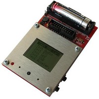
STM32-103STK
Manufacturer Part Number
STM32-103STK
Description
MCU, MPU & DSP Development Tools STARTERKIT BRD FOR STM32F103RBT6
Manufacturer
Olimex Ltd.
Datasheet
1.STM32-103STK.pdf
(16 pages)
Specifications of STM32-103STK
Processor To Be Evaluated
STM32F103RBT6
Data Bus Width
32 bit
Interface Type
USB, CAN, I2C, JTAG, SPI, UART
Dimensions
90 mm x 65 mm
Operating Supply Voltage
1.5 V
Silicon Manufacturer
ST Micro
Core Architecture
ARM
Core Sub-architecture
Cortex - M3
Silicon Core Number
STM32
Silicon Family Name
STM32F1xx
Rohs Compliant
Yes
Lead Free Status / RoHS Status
Lead free / RoHS Compliant
Other names
1701515 25R5111


CONNECTOR DESCRIPTION:
JTAG:
TMS
TCK
TDI
TDO
TRST
Pin #
JTAG CONNECTOR PIN DESCRIPTIONS
11
13
15
17
19
1
3
5
7
9
Input
Input
Input
Output Test Data Output. This is the serial data output from the shift register. Data is shifted out of the
Input
Signal Name
TVCC 3.3V
Test Mode Select. The TMS pin selects the next state in the TAP state machine.
Test Clock. This allows shifting of the data in, on the TMS and TDI pins.
It is a positive edgetriggered clock with the TMS and TCK signals that define the internal state
of the device.
Test Data In. This is the serial data input for the shift register.
device on the negative edge of the TCK signal.
Test Reset. The TRST pin can be used to reset the test logic within the EmbeddedICE logic.
TRST
TMS
TDO
TCK
RST
Audio Out
SD-MMC card connected to SPI2;
nRF24L01
Power supply red LED with name PWR – indicates that 3.3V power supply
is applied.
TDI
NC
NC
NC
Pin #
10
12
14
16
18
20
2
4
6
8
audio amplifier connected to PA8 PWM output;
connected to SPI1;
Signal Name
TVCC 3.3V
GND
GND
GND
GND
GND
GND
GND
GND
GND
Related parts for STM32-103STK
Image
Part Number
Description
Manufacturer
Datasheet
Request
R

Part Number:
Description:
DEV KIT FOR STM32
Manufacturer:
STMicroelectronics
Datasheet:

Part Number:
Description:
MCU ARM 128KB FLASH MEM 64-LQFP
Manufacturer:
STMicroelectronics
Datasheet:

Part Number:
Description:
MCU ARM 32BIT 128KB FLASH 64BGA
Manufacturer:
STMicroelectronics
Datasheet:

Part Number:
Description:
MCU ARM 32BIT 256K FLASH 144LQFP
Manufacturer:
STMicroelectronics
Datasheet:

Part Number:
Description:
KIT STARTER FOR STM32F10X
Manufacturer:
STMicroelectronics
Datasheet:

Part Number:
Description:
MCU ARM 128K FLASH/TIMER
Manufacturer:
STMicroelectronics
Datasheet:

Part Number:
Description:
MCU ARM 128KB FLASH MEM 100-LQFP
Manufacturer:
STMicroelectronics
Datasheet:

Part Number:
Description:
MCU 32BIT ARM 64K FLASH 36VFQFPN
Manufacturer:
STMicroelectronics
Datasheet:
Part Number:
Description:
MCU ARM 32BIT 32KB FLASH 48LQFP
Manufacturer:
STMicroelectronics
Datasheet:
Part Number:
Description:
MCU ARM 32BIT 64KB FLASH 64LQFP
Manufacturer:
STMicroelectronics
Datasheet:
Part Number:
Description:
MCU ARM 32BIT 384KB FLASH 64LQFP
Manufacturer:
STMicroelectronics
Datasheet:

Part Number:
Description:
MCU 32BIT ARM 512K FLASH 100-LQF
Manufacturer:
STMicroelectronics
Datasheet:
Part Number:
Description:
MCU ARM 32BIT 512KB FLASH 144BGA
Manufacturer:
STMicroelectronics
Datasheet:
Part Number:
Description:
MCU ARM 32BIT 512K FLASH 144LQFP
Manufacturer:
STMicroelectronics
Datasheet:
Part Number:
Description:
MCU 32BIT ARM 16K FLASH 64LQFP
Manufacturer:
STMicroelectronics
Datasheet: