UM232R FTDI, UM232R Datasheet - Page 10
UM232R
Manufacturer Part Number
UM232R
Description
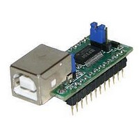
Interface Modules & Development Tools USB to Serial UART Dev Mod for FT232R
Manufacturer
FTDI
Type
Development Moduler
Specifications of UM232R
Interface Type
USB, Serial, UART
Data Bus Width
Serial
Operating Supply Voltage
1.8 V to 5.25 V
Product
Interface Modules
Supported Devices
FT232R
Svhc
No SVHC (18-Jun-2010)
Development Tool Type
Development Kit
Kit Features
Single Chip USB To Asynchronous Serial Data Transfer Interface, Auto Transmit Buffer
Rohs Compliant
Yes
Supported Families
FT232RL
Features
Single Chip USB To Asynchronous Serial Data Transfer Interface, Auto Transmit Buffer Control
Tool / Board Applications
USB To
For Use With/related Products
FT232R
Lead Free Status / RoHS Status
Lead free / RoHS Compliant


Pin No.
22
23
Table 4.1Module Pin Out Description
* When used in Suspend, these pins are pulled to VCCIO via internal 200kΩ resistors. These pins
can be programmed to gently pull low during USB suspend (PWREN# = “1”) by setting an option
in the internal EEPROM.
4.3 Jumper Configuration Options
Pin No.
1
2
3
Table 4.2 Jumper J1 Pin Description
Pin No.
1
2
Table 4.3 Jumper J2 Pin Description
© Copyright 2009 Future Technology Devices International Ltd
Name
CB1
CB0
Name
3V3
VIO
VCC
Name
USB
VCC
Type
I/O
I/O
Type
Output
PWR
PWR
Type
PWR
PWR or
Output
Description
unconnected, or pulled up to VCCIO.
Configurable CBUS I/O Pin. Function of this pin is configured in the device internal
EEPROM. Factory Default pin Function is RXLED#. See CBUS Signal Options, Table
4.4.*
Configurable CBUS I/O Pin. Function of this pin is configured in the device internal
EEPROM. Factory Default pin Function is TXLED#. See CBUS Signal Options,Table 4.4.*
Description
Connect this pin to pin 2 to create 3V3 I/O.
Input Pin for Chip VCCIO
Connect this pin to pin 2 to create 5V I/O
Description
5V Power output USB port. For a low power USB bus power design, up to 100mA can
be sourced from the 5V supply on the USB bus. A maximum of 500 mA can be sourced
from the USB bus in a high power USB bus powered design.
Board supply input. Connect to jumper J2 pin 1 in order to supply the board from the
USB bus.
This pin is internally connected to the VCC DIP pins. Remove the jumper connector in a
self powered design.
UM232R USB - Serial UART Development Module Incorporating Clock Generator
Document Reference No.: FT_000051
Clearance No.: FTDI# 125
Datasheet Version 1.04
9
Related parts for UM232R
Image
Part Number
Description
Manufacturer
Datasheet
Request
R

Part Number:
Description:
Interface Modules & Development Tools USB to Serial UART MiniB Dev Mod FT232R
Manufacturer:
FTDI
Datasheet:

Part Number:
Description:
BOARD, EVALUATION, EU PSU
Manufacturer:
FTDI
Datasheet:
Part Number:
Description:
BOARD, EVALUATION, UK PSU
Manufacturer:
FTDI
Datasheet:
Part Number:
Description:
BOARD, EVALUATION, US PSU
Manufacturer:
FTDI
Datasheet:
Part Number:
Description:
Specifications: Manufacturer: FTDI ; Product Category: USB Interface IC ; RoHS: Details ; Operating Supply Voltage: 3 V to 5.25 V ; Supply Current: 25 mA ; Maximum Operating Temperature: + 70 C ; Mounting Style: SMD/SMT ; Package / Case: QFN-32
Manufacturer:
FTDI
Part Number:
Description:
integr. usb2.0/uart lqfp32 rohs ftdi reel c1k...
Manufacturer:
FTDI
Datasheet:
Part Number:
Description:
Interface Development Tools USB to UART Breakout Board
Manufacturer:
FTDI
Datasheet:

Part Number:
Description:
IC USB TO SERIAL UART 32-QFN
Manufacturer:
FTDI, Future Technology Devices International Ltd

Part Number:
Description:
USB Interface IC USB to Serial UART Enhanced IC SSOP-28
Manufacturer:
FTDI
Datasheet:

Part Number:
Description:
IC, USB UART INTERFACE, SSOP-28
Manufacturer:
FTDI
Datasheet:

Part Number:
Description:
IC, USB UART INTERFACE, QFN-32
Manufacturer:
FTDI
Datasheet:
Part Number:
Description:
IC, USB FIFO INTERFACE, SSOP-28
Manufacturer:
FTDI
Datasheet:
Part Number:
Description:
MODULE, USB, 4 PORT, FT4232H BASED
Manufacturer:
FTDI
Datasheet:
Part Number:
Description:
357-036-542-201 CARDEDGE 36POS DL .156 BLK LOPRO
Manufacturer:
FTDI
Datasheet:
Part Number:
Description:
357-036-542-201 CARDEDGE 36POS DL .156 BLK LOPRO
Manufacturer:
FTDI
Datasheet: