UM245R FTDI, UM245R Datasheet - Page 26
UM245R
Manufacturer Part Number
UM245R
Description
Interface Modules & Development Tools USB to Parallel FIFO Dev Mod for FT245R
Manufacturer
FTDI
Type
Development Moduler
Datasheet
1.UM245R.pdf
(27 pages)
Specifications of UM245R
Interface Type
USB, Parallel FIFO
Data Bus Width
8 bit
Operating Supply Voltage
1.8 V to 5.25 V
Product
Interface Modules
Supported Devices
FT245R
Svhc
No SVHC (18-Jun-2010)
Development Tool Type
Development Kit
Kit Features
Single Chip USB To Parallel FIFO Bidirectional Data Transfer Interface
Rohs Compliant
Yes
Mcu Supported Families
FT245RL
Supported Families
FT245RL
Tool / Board Applications
USB To Parallel FIFO Interface
For Use With/related Products
FT245R
Lead Free Status / RoHS Status
Lead free / RoHS Compliant


Document Reference No.: FT_000202
UM245R USB - Parallel FIFO Development Module Datasheet Version 1.04
Clearance No.: FTDI# 124
Appendix A – List of Tables and Figures
List of Table
Table 4.1 Module Pin-Out Description .......................................................................................................... 9
Table 4.2 Jumper J1 Pin Description ............................................................................................................ 9
Table 4.3 Jumper J2 Pin Description ............................................................................................................ 9
Table 4.4 FIFO Read Cycle Timings ............................................................................................................ 10
Table 4.5 FIFO Write Cycle Timings ........................................................................................................... 11
Table 6.1 Absolute Maximum Ratings ........................................................................................................ 13
Table 6.2 Operating Voltage and Current ................................................................................................... 13
Table 6.3 FIFO Interface and Control Bus Pin Characteristics (VCCIO = 5.0V, Standard Drive Level) ........ 14
Table 6.4 FIFO Interface and Control Bus Pin Characteristics (VCCIO = 3.3V, Standard Drive Level) ........ 14
Table 6.5 FIFO Interface and Control Bus Pin Characteristics (VCCIO = 2.8V, Standard Drive Level) ........ 14
Table 6.6 FIFO Interface and Control Bus Pin Characteristics (VCCIO = 5.0V, High Drive Level) ............... 15
Table 6.7 FIFO Interface and Control Bus Pin Characteristics (VCCIO = 3.3V, High Drive Level) ............... 15
Table 6.8 FIFO Interface and Control Bus Pin Characteristics (VCCIO = 2.8V, High Drive Level) ............... 15
Table 6.9 RESET# and TEST Pin Characteristics ......................................................................................... 15
Table 6.10 USB I/O Pin (USBDP, USBDM) Characteristics ......................................................................... 16
Table 6.11 EEPROM Characteristics ........................................................................................................... 16
Table 6.12 Internal Clock Characteristics .................................................................................................. 17
Table 9.1 Default Internal EEPROM Configuration ..................................................................................... 23
List of Table
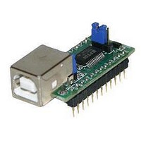
Figure 1.1 – UM245R USB to Parallel FIFO Development Module ................................................................. 1
Figure 4.1 Module Pin Out and Jumper Locations ........................................................................................ 7
Figure 4.2 FIFO Read Cycle ........................................................................................................................ 10
Figure 4.3 FIFO Write Cycle ....................................................................................................................... 11
Figure 5.1 UM245R Module Dimensions ..................................................................................................... 12
Figure 7.1 Bus Powered Configuration ...................................................................................................... 18
Figure 7.2 Self-Powered Configuration ...................................................................................................... 19
Figure 7.3 Bus Powered with Power Switching Configuration ................................................................... 20
Figure 7.4 USB Bus Powered 3.3V Logic Drive ........................................................................................... 21
Figure 8.1 Module Circuit Schematic .......................................................................................................... 22
© Copyright 2009 Future Technology Devices International Ltd
25
Related parts for UM245R
Image
Part Number
Description
Manufacturer
Datasheet
Request
R

Part Number:
Description:
Interface Modules & Development Tools USB to Serial UART MiniB Dev Mod FT232R
Manufacturer:
FTDI
Datasheet:

Part Number:
Description:
BOARD, EVALUATION, EU PSU
Manufacturer:
FTDI
Datasheet:
Part Number:
Description:
BOARD, EVALUATION, UK PSU
Manufacturer:
FTDI
Datasheet:
Part Number:
Description:
BOARD, EVALUATION, US PSU
Manufacturer:
FTDI
Datasheet:
Part Number:
Description:
Specifications: Manufacturer: FTDI ; Product Category: USB Interface IC ; RoHS: Details ; Operating Supply Voltage: 3 V to 5.25 V ; Supply Current: 25 mA ; Maximum Operating Temperature: + 70 C ; Mounting Style: SMD/SMT ; Package / Case: QFN-32
Manufacturer:
FTDI
Part Number:
Description:
integr. usb2.0/uart lqfp32 rohs ftdi reel c1k...
Manufacturer:
FTDI
Datasheet:
Part Number:
Description:
Interface Development Tools USB to UART Breakout Board
Manufacturer:
FTDI
Datasheet:

Part Number:
Description:
IC USB TO SERIAL UART 32-QFN
Manufacturer:
FTDI, Future Technology Devices International Ltd

Part Number:
Description:
USB Interface IC USB to Serial UART Enhanced IC SSOP-28
Manufacturer:
FTDI
Datasheet:

Part Number:
Description:
IC, USB UART INTERFACE, SSOP-28
Manufacturer:
FTDI
Datasheet:

Part Number:
Description:
IC, USB UART INTERFACE, QFN-32
Manufacturer:
FTDI
Datasheet:
Part Number:
Description:
IC, USB FIFO INTERFACE, SSOP-28
Manufacturer:
FTDI
Datasheet:
Part Number:
Description:
MODULE, USB, 4 PORT, FT4232H BASED
Manufacturer:
FTDI
Datasheet:
Part Number:
Description:
357-036-542-201 CARDEDGE 36POS DL .156 BLK LOPRO
Manufacturer:
FTDI
Datasheet:
Part Number:
Description:
357-036-542-201 CARDEDGE 36POS DL .156 BLK LOPRO
Manufacturer:
FTDI
Datasheet: