28560 Parallax Inc, 28560 Datasheet - Page 3
28560
Manufacturer Part Number
28560
Description
Interface Modules & Development Tools Mouse Sensor Kit
Manufacturer
Parallax Inc
Datasheet
1.28560.pdf
(18 pages)
Specifications of 28560
Interface Type
Serial
Operating Supply Voltage
5 V
Product
Interface Modules
Lead Free Status / RoHS Status
Lead free / RoHS Compliant


For Operation
Assembly Instructions
Assemble the Circuit Board
Copyright © Parallax Inc.
•
•
•
1. The printed circuit board is marked on top with the part numbers from the “Part” column in the
2. Install and solder all the parts,
3. Take the LED and insert it into the right-angle holder, being sure to position the longer, positive
4. With the needle-nosed pliers, grab the leads and pull the LED against the holder until it’s firmly
NOTE: The LED is shown in the drawings with a red lens. The LED provided may be red or clear.
BASIC Stamp, Propeller, SX, etc.
Carrier board (e.g. Board of Education, Propeller Demo Board, Propeller Proto Board, etc.)
One or two servo extension cables with 3-pin headers (e.g. Parallax #805-00011)
table above. Here is an illustration of the unpopulated circuit board:
the polarity of D1 (stripe goes to the right) and of C1 (positive lead – the longer one – goes to
the top). Take your time and make sure that all parts are firmly seated against the board. For J1
and J2, solder the diagonal corner pins first and check the seating. If a header is crooked or not
all the way in, you have a chance to reheat the joints and make adjustments. Once these
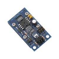
headers are seated correctly, you can solder the remaining pins. Here’s what the board will look
like:
lead as shown:
seated. Then, still pulling with the pliers, bend the leads sharply downward:
except
Mouse Sensor Kit (#28560)
U1 and LED1, as shown below, paying close attention to
v1.0 6/1/2010 Page 3 of 18
Related parts for 28560
Image
Part Number
Description
Manufacturer
Datasheet
Request
R


Part Number:
Description:
Microcontroller Modules & Accessories DISCONTINUED BY PARALLAX
Manufacturer:
Parallax Inc

Part Number:
Description:
BOOK UNDERSTANDING SIGNALS
Manufacturer:
Parallax Inc
Datasheet:


Part Number:
Description:
COMPETITION RING FOR SUMOBOT
Manufacturer:
Parallax Inc
Datasheet:


Part Number:
Description:
TEXT INFRARED REMOTE FOR BOE-BOT
Manufacturer:
Parallax Inc
Datasheet:
Part Number:
Description:
BOARD EXPERIMENT+LCD NX-1000
Manufacturer:
Parallax Inc
Datasheet:

Part Number:
Description:
CONTROLLER 16SERVO MOTOR CONTROL
Manufacturer:
Parallax Inc
Datasheet:

Part Number:
Description:
BASIC STAMP LOGIC ANALYZER
Manufacturer:
Parallax Inc
Datasheet:

Part Number:
Description:
IC MCU 2K FLASH 50MHZ SO-18
Manufacturer:
Parallax Inc
Datasheet: