EE-SY672 Omron, EE-SY672 Datasheet
EE-SY672
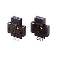
Specifications of EE-SY672
Available stocks


Related parts for EE-SY672


EE-SY672 Summary of contents
Page 1
... Refer to Accessories for details. Sensing distance Output type NPN output Cable length Model EE-1001 L terminal and positive (+) terminal are already EE-1001-1 short-circuited. EE-1009 EE-1006 1 m EE-1010 EE-1006 2 m EE-1010 1 m EE-1010 EE-1010-R CSM_EE-SY671_672_DS_E_3_1 Infrared light Output Model configuration EE-SY671 Dark-ON or Light-ON (Selectable) * EE-SY672 Remarks 1 ...
Page 2
... Approx. 3.5 g (including screwdriver for adjustment) Case Polybutylene phthalate (PBT) Material Emitter/ Polycarbonate receiver Accessories Screwdriver for adjustment EE-SY671, EE-SY672 for 3 times each and Z directions EE-SY671/672 *1. The indicator is a GaP red LED (peak wavelength: 690 nm). *2. The response frequency was measured by detecting the following rotating disk ...
Page 3
... NPN Output Output Model Timing charts configuration Incident Interrupted Light indicator (red) Light-ON Output transistor Load 1 Operates (relay) EE-SY671 Releases EE-SY672 Incident Interrupted Light indicator (red) Dark-ON Output transistor Load 1 Operates (relay) Releases EE-SY67@ 22 Sensing object: White paper (15 × (reflection factor: 90%) ...
Page 4
... Wiring Soldering • When direct soldering to the terminal, use the following guidelines. Soldering Conditions Permissible Item Temperature time The portion between the base of Soldering 350°C the terminals and the position 3 s max. iron max. 1.5 mm from the terminal base must not be soldered. • ...
Page 5
... Point B Check Set the sensitivity adjuster 3. After setting the sensitivity at the center (point C) adjuster to point C, check if between points A and B (the the light indicator is not lit on point where the sensitivity is removing the sensing maximum). object. EE-SY671/672 Check ...
Page 6
... Indicator window Terminal Arrangement Accessories (Order Separately) * Refer to Accessories for details. Tolerance class IT16 applies to dimensions in this datasheet unless otherwise specified. EE-SY672 Two, 3.2 dia. holes Sensing window (back) (12.2 × 4.1) Sensitivity 6.95 adjuster 6.35 4.1 Two, 3.8 dia. ...
Page 7
... Please read and understand this catalog before purchasing the products. Please consult your OMRON representative if you have any questions or comments. WARRANTY OMRON's exclusive warranty is that the products are free from defects in materials and workmanship for a period of one year (or other period if specified) from date of sale by OMRON. OMRON MAKES NO WARRANTY OR REPRESENTATION, EXPRESS OR IMPLIED, REGARDING NON-INFRINGEMENT, MERCHANTABILITY, OR FITNESS FOR PARTICULAR PURPOSE OF THE PRODUCTS ...