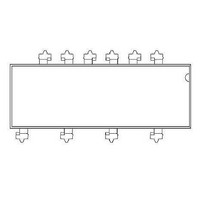
VO3526 Vishay, VO3526 Datasheet - Page 2

VO3526
Manufacturer Part Number
VO3526
Description
Triac & SCR Output Optocouplers 1.0A Load Current Power Phototriac
Manufacturer
Vishay
Datasheet
1.VO3526.pdf
(8 pages)
Specifications of VO3526
Isolation Voltage
5300 V
Package / Case
DIP-10
Configuration
1 Channel
Maximum Continuous Output Current
1 A
Maximum Input Current
50 mA
Maximum Operating Temperature
+ 85 C
Maximum Power Dissipation
1.2 W
Maximum Reverse Diode Voltage
5 V
Minimum Operating Temperature
- 40 C
Mounting Style
SMD/SMT
Zero-crossing Circuit
No
Output Device
PhotoTriac
Peak Output Voltage (vdrm)
600 V
Maximum Input Voltage
1.4 V
Maximum Output Voltage
600 V
No. Of Channels
1
Optocoupler Output Type
Phototriac
Input Current
10mA
Output Voltage
1.7V
Opto Case Style
DIP
No. Of Pins
10
Output Type
Phototriac
Rohs Compliant
Yes
Lead Free Status / RoHS Status
Lead free / RoHS Compliant
Lead Free Status / RoHS Status
Lead free / RoHS Compliant, Lead free / RoHS Compliant
VO3526
Vishay Semiconductors
ABSOLUTE MAXIMUM RATING CURVES
Note
The thermal model is represented in the thermal network below.
Each resistance value given in this model can be used to calculate
the temperatures at each node for a given operating condition. The
thermal resistance from board to ambient will be dependent on the
type of PCB, layout and thickness of copper traces. For a detailed
explanation of the thermal model, please reference Vishay's
Thermal Characteristics of Power Phototriac application note.
www.vishay.com
2
THERMAL CHARACTERISTICS
PARAMETER
Maximum LED
junction temperature
Maximum NOT
junction temperature
Thermal resistance,
junction NOT to bord
Thermal resistance,
junction NOT to case
Thermal resistance,
junction OT to board
Thermal resistance,
junction OT to case
Thermal resistance,
junction emitter to board
Thermal resistance,
junction emitter to case
Thermal resistance,
junction NOT to junction OT
Thermal resistance,
junction emitter to junction NOT
Thermal resistance,
junction emitter to junction OT
Thermal resistance,
case to ambient
21296
Fig. 1 - Power Dissipation vs. Temperature
80
60
40
20
0
- 40
- 20
T
A
- Ambient Temperature (°C)
0
20
40
SYMBOL VALUE
θ
θ
θ
θ
For technical questions, contact: optocoupler.answers@vishay.com
T
T
θ
NOT-OT
θ
θ
NOT-B
NOT-C
θ
θ
E-NOT
θ
OT-B
OT-C
E-OT
60
jmax.
jmax.
E-B
E-C
CA
80
100
105
105
150
158
157
149
161
243
420
235
130
75
120
°C/W
°C/W
°C/W
°C/W
°C/W
°C/W
°C/W
°C/W
°C/W
°C/W
UNIT
Power Phototriac
°C
°C
Note
The allowable load current was calculated out under a given
operating conditions and only for reference:
LED power: Q
NOT:
OT:
T
T
T
θ
Q
Q
Q
BA
θ
B
CASE
A
E
OT
NOT
21295
NOT-B
:
:
:
:
T
:
Fig. 2 - Allowable Load Current vs. Ambient Temperature
:
B
: Case temperature
21502
T
Non-opto-triac
Opto-triac
Board temperature
Ambient temperature
Thermal resistance, board to ambient
LED power dissipation
OT power dissipation
NOT power dissipation
θ
NOT
θ
E-NOT
E-B
1.0
1.2
0.8
0.6
0.4
0.2
T
Q
0
E
T
- 40 - 20
CASE
θ
NOT
= 0.015 W,
B
NOT-C
Q
θ
NOT-OT
E
Ambient Temperature (°C)
θ
T
OT-C
0
E
Q
Thermal Model
θ
OT
BA
θ
20
θ
E-C
E-OT
T
(4-layer) = 30 °C/W
T
T
CASE
OT
CASE
40
θ
60
OT-B
θ
T
Document Number: 81842
T
BA
B
Thermal Model
B
80 100 120
Power Triac
Rev. 1.2, 23-Oct-08
T
A
T
CASE
θ
CA


