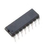
K844P Vishay, K844P Datasheet

K844P
Specifications of K844P
Related parts for K844P
K844P Summary of contents
Page 1
... C DESCRIPTION The K814P, K824P, K844P consist of a phototransistor optically coupled to 2 gallium arsenide infrared emitting diodes (reverse polarity pin (single); 8 pin (dual) or 16-pin (quad) plastic dual inline package. The elements are mounted on one leadframe providing a fixed distance between input and output for highest safety requirements ...
Page 2
... K814P, K824P, K844P Vishay Semiconductors ABSOLUTE MAXIMUM RATINGS PARAMETER COUPLER AC isolation test voltage (RMS) Total power dissipation Operating ambient temperature range Storage temperature range (3) Soldering temperature Notes ( °C, unless otherwise specified. amb Stresses in excess of the absolute maximum ratings can cause permanent damage to the device. Functional operation of the device is not implied at these or any other conditions in excess of those given in the operational sections of this document ...
Page 3
... Optocoupler, Phototransistor Output, AC Input 100 % input amplitude Oscilloscope R > 1 MΩ < Oscilloscope R > < 1000 100 10 0.1 120 96 11862 Fig Forward Current vs. Forward Voltage K814P, K824P, K844P Vishay Semiconductors off on Pulse duration t Storage time s Delay time t Fall time f Rise time Turn-off time ...
Page 4
... K814P, K824P, K844P Vishay Semiconductors 2.0 1.5 1.0 0 Ambient Temperature (°C) 95 11025 amb Fig Relative Current Transfer Ratio vs. Ambient Temperature 10 000 1000 100 Ambient Temperature (°C) 95 11026 amb Fig Collector Dark Current vs. Ambient Temperature 100 0.1 0.01 0 Forward Current (mA) 95 11027 F Fig ...
Page 5
... Optocoupler, Phototransistor Output, AC Input t off 11030 Fig Turn-on/Turn-off Time vs. Collector Current < 4.75 6.3 ± 0.1 4.5 ± 0.2 9 ± 0.8 1.32 ± 0.05 E. g.: Special features: endstackable to 2.54 mm (0.100") spacing 2.54 2.54 K814P, K824P, K844P Vishay Semiconductors 10 Non-saturated operation 100 Ω off ...
Page 6
... K814P, K824P, K844P Vishay Semiconductors 19.7 ± 0.2 0.53 ± 0.05 2.54 nom 2.54 = 17. 0.53 ± 0.05 2.54 nom. www.vishay.com For technical questions, contact: optocoupler.answers@vishay.com 536 Optocoupler, Phototransistor Output, AC Input < 20 1.32 ± 0.05 Weight: ca. 1.08 g Creepage distance: > Air path: > after mounting on PC board ...
Page 7
... Vishay Semiconductor GmbH, P.O.B. 3535, D-74025 Heilbronn, Germany Document Number: 83523 For technical questions, contact: optocoupler.answers@vishay.com Rev. 2.1, 10-Dec-08 Optocoupler, Phototransistor Output, AC Input and may do so without further notice. K814P, K824P, K844P Vishay Semiconductors www.vishay.com 537 ...
Page 8
... Vishay product could result in personal injury or death. Customers using or selling Vishay products not expressly indicated for use in such applications their own risk and agree to fully indemnify and hold Vishay and its distributors harmless from and against any and all claims, liabilities, expenses and damages arising or resulting in connection with such use or sale, including attorneys fees, even if such claim alleges that Vishay or its distributor was negligent regarding the design or manufacture of the part ...


