E3Z-LS61 Omron, E3Z-LS61 Datasheet - Page 9
E3Z-LS61
Manufacturer Part Number
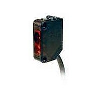
E3Z-LS61
Description
Industrial Photoelectric Sensors BGS/FGS NPN Output Diffuse pre-wired
Manufacturer
Omron
Type
Photoelectric Sensorsr
Series
E3Zr
Specifications of E3Z-LS61
Features
Adjustable sensing distance
Output
NPN
Sensing Method
Diffuse Reflective
Sensing Distance
20 mm to 200 mm
Light Source
Red LED
Connection
Prewired Cable
Output Configuration
NPN
Sensing Range
20mm To 200mm
Output Current
100mA
Sensor Output
NPN
Supply Voltage Range Dc
12V To 24V
Output Type
Transistor
Sensor Input
Optical
Supply Voltage Max
24VDC
Sensing Range Max
200mm
Sensing Object
White Paper
Sensing Light
Red
Mounting Type
Bracket Mount
Current - Supply
30mA
Voltage - Supply
12 V ~ 24 V
Package / Case
Module, Pre-Wired
Lead Free Status / RoHS Status
Lead free / RoHS Compliant
Lead Free Status / RoHS Status
Lead free / RoHS Compliant, Lead free / RoHS Compliant
Available stocks
Company
Part Number
Manufacturer
Quantity
Price
Company:

Part Number:
E3Z-LS61
Manufacturer:
OMRON
Quantity:
1 000
Company:
Part Number:
E3Z-LS61
Manufacturer:
OMRON
Quantity:
384


Precautions
Be sure to abide by the following precautions for the safe operation of
the Sensor.
Wiring
Power Supply Voltage and Output Load
Power Supply Voltage
Make sure that the power supply to the Sensor is within the rated
voltage range. If a voltage exceeding the rated voltage range is sup-
plied to the Sensor, it may explode or burn.
Load Short-circuiting
Do not short-circuit the load, otherwise the Sensor may be damaged.
Connection without Load
Do not connect the power supply to the Sensor with no load con-
nected, otherwise the internal elements may explode or burn.
Operating Environment
Do not use the Sensor in locations with explosive or flammable gas.
■ Correct Use
Design
Power Reset Time
The Sensor is ready to operate 100 ms after the Sensor is turned
ON. If the load and Sensor are connected to independent power sup-
plies respectively, be sure to turn ON the Sensor before supplying
power to the load.
Wiring
Avoiding Malfunctions
If using the Photoelectric Sensor with an inverter or servomotor,
always ground the FG (frame ground) and G (ground) terminals, oth-
erwise the Sensor may malfunction.
Mounting
Mounting the Sensor
• If Sensors are mounted face-to-face, make sure that the optical
• Always install the Sensor carefully so that the aperture angle range
• Do not strike the Photoelectric Sensor with a hammer or any other
• Use M3 screws to mount the Sensor.
• When mounting the case, make sure that the tightening torque
Do not connect an AC power supply to the Sensor. If AC power
(100 VAC or more) is supplied to the Sensor, it may explode or
burn.
axes are not in opposition to each other. Otherwise, mutual interfer-
ence may result.
of the Sensor will not cause it to be directly exposed to intensive
light, such as sunlight, fluorescent light, or incandescent light.
tool during the installation of the Sensor, or the Sensor will lose its
water-resistive properties.
applied to each screw does not exceed 0.54 N·m.
!Caution
Distance-settable Photoelectric Sensor
M8 Connector
• Always turn OFF the power supply to the Sensor before connecting
• Hold the connector cover to connect or disconnect it.
• Secure the connector cover by hand. Do not use pliers, otherwise
• If the connector is not connected securely, it may be disconnected
Mounting Directions
• Make sure that the sensing side of the Sensor is parallel with the
If the sensing object has a glossy surface, however, incline the Sen-
sor by 5° to 10° as shown in the illustration, provided that the Sensor
is not influenced by background objects.
• If there is a mirror-like object below the Sensor, the Sensor may not
• Do not install the Sensor in the wrong direction. Refer to the follow-
or disconnecting the metal connector.
the connector may be damaged.
by vibration or the proper degree of protection of the Sensor may
not be maintained.
surface of the sensing objects. Normally, do not incline the Sensor
towards the sensing object.
operate stably. Therefore, incline the Sensor or separate the Sen-
sor from the mirror-like object as shown below.
ing illustration.
Sensing
object
Moving direction
Sensing object
Moving direction
Surface of sensing object
Mirror-like object
Sensing side
Sensing
object
Glossy object
E3Z-LS
Moving direction
Sensing
object
9
Related parts for E3Z-LS61
Image
Part Number
Description
Manufacturer
Datasheet
Request
R

Part Number:
Description:
EMITTER ONLY FOR E3Z-T61
Manufacturer:
Omron
Datasheet:

Part Number:
Description:
Sensor; NPN/PNP; Photoelectric; 100 mm to 4 m; Red; 12 to 24 VDC 10 %; ABS
Manufacturer:
Omron Automation
Datasheet:
Part Number:
Description:
Sensor; PNP; Polarized Retroreflective Sensing Mode; Photoelectric; 30 mA; 1 ms
Manufacturer:
Omron Automation
Datasheet:

Part Number:
Description:
Photoelectric Sensors - Industrial Emitter Only for E3Z -T81
Manufacturer:
Omron
Datasheet:
Part Number:
Description:
LaserType TB,emit Only M12 NPN
Manufacturer:
Omron
Datasheet:
Part Number:
Description:
Thru Beam Sensor
Manufacturer:
Omron
Datasheet:
Part Number:
Description:
Cable
Manufacturer:
Omron
Datasheet:
Part Number:
Description:
Industrial Photoelectric Sensors NPN DIFF REFLECTIVE
Manufacturer:
Omron
Datasheet:

Part Number:
Description:
Industrial Photoelectric Sensors BGS/FGS NPN Output Diffuse M8 Connector
Manufacturer:
Omron
Datasheet:
Part Number:
Description:
G6S-2GLow Signal Relay
Manufacturer:
Omron Corporation
Datasheet:
Part Number:
Description:
Compact, Low-cost, SSR Switching 5 to 20 A
Manufacturer:
Omron Corporation
Datasheet:
Part Number:
Description:
Manufacturer:
Omron Corporation
Datasheet: