VBPW34SR Vishay, VBPW34SR Datasheet - Page 2
VBPW34SR
Manufacturer Part Number
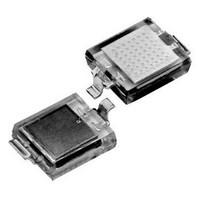
VBPW34SR
Description
Photodiodes 60V 215mW 65Deg
Manufacturer
Vishay
Type
PIN Photodioder
Specifications of VBPW34SR
Lens Type
Transparent
Photodiode Material
Silicon
Peak Wavelength
940 nm
Half Intensity Angle Degrees
65 deg
Maximum Reverse Voltage
60 V
Maximum Power Dissipation
215 mW
Maximum Light Current
55 uA
Maximum Dark Current
30 nA
Maximum Rise Time
100 ns
Maximum Fall Time
100 ns
Wavelength Typ
940nm
Half Angle
65°
Dark Current
2nA
Diode Case Style
SMD
No. Of Pins
2
Operating Temperature Range
-40°C To +100°C
Msl
MSL 3 - 168 Hours
Reverse Voltage Vr
60V
Breakdown Voltage Vbr
60V
Reverse Voltage Vr Max
60V
Rohs Compliant
Yes
Forward Voltage Vf Max
1.3V
Featured Product
VBPW34x / VBP104x Series High-Speed PIN Photodiodes
Wavelength
940nm
Output Type
Current On Typ, 55µA
Package / Case
2-SMD, Z-Bend
Svhc
No SVHC (20-Jun-2011)
Lead Free Status / RoHS Status
Lead free / RoHS Compliant
Lead Free Status / RoHS Status
Lead free / RoHS Compliant, Lead free / RoHS Compliant
Available stocks
Company
Part Number
Manufacturer
Quantity
Price
Company:

Part Number:
VBPW34SR
Manufacturer:
ON
Quantity:
46 000
Part Number:
VBPW34SR
Manufacturer:
VISHAY/威世
Quantity:
20 000


VBPW34S, VBPW34SR
Vishay Semiconductors
BASIC CHARACTERISTICS (T
www.vishay.com
2
BASIC CHARACTERISTICS (T
PARAMETER
Forward voltage
Breakdown voltage
Reverse dark current
Diode capacitance
Open circuit voltage
Temperature coefficient of V
Short circuit current
Temperature coefficient of I
Reverse light current
Angle of half sensitivity
Wavelength of peak sensitivity
Range of spectral bandwidth
Noise equivalent power
Rise time
Fall time
Fig. 1 - Reverse Dark Current vs. Ambient Temperature
94 8403
1000
100
10
1
20
T
amb
40
- Ambient Temperature (°C)
k
o
60
For technical questions, contact:
V
R
= 10 V
E
E
E
E
E
amb
80
V
V
e
e
e
e
e
amb
R
R
= 1 mW/cm
V
= 1 mW/cm
= 1 mW/cm
= 1 mW/cm
= 1 mW/cm
V
V
= 0 V, f = 1 MHz, E = 0
= 3 V, f = 1 MHz, E = 0
R
TEST CONDITION
R
R
I
= 25 °C, unless otherwise specified)
R
V
= 10 V, λ = 950 nm
= 10 V, R
= 10 V, R
= 25 °C, unless otherwise specified)
= 100 µA, E = 0
R
λ = 820 nm
λ = 820 nm
I
= 10 V, E = 0
F
V
Silicon PIN Photodiode
100
= 50 mA
R
= 5 V
2
2
2
2
2
, λ = 950 nm,
, λ = 950 nm
, λ = 950 nm
, λ = 950 nm
, λ = 950 nm
L
L
= 1 kΩ,
= 1 kΩ,
detectortechsupport@vishay.com
Fig. 2 - Relative Reverse Light Current vs. Ambient Temperature
SYMBOL
V
TK
NEP
TK
λ
C
C
V
V
(BR)
I
I
λ
I
ϕ
0.1
t
t
ro
ra
k
r
D
D
p
f
F
o
Vo
Ik
94 8409
1.4
1.2
1.0
0.8
0.6
0
MIN.
60
45
T
20
amb
- Ambient Temperature (°C)
430 to 1100
4 x 10
λ = 950 nm
V
40
TYP.
- 2.6
± 65
350
940
100
100
0.1
R
70
25
50
55
1
2
= 5 V
-14
60
Document Number: 81128
MAX.
1.3
30
40
80
Rev. 1.1, 20-Apr-10
100
W/√Hz
mV/K
UNIT
%/K
deg
mV
nm
nm
nA
µA
µA
pF
pF
ns
ns
V
V
Related parts for VBPW34SR
Image
Part Number
Description
Manufacturer
Datasheet
Request
R

Part Number:
Description:
357-036-542-201 CARDEDGE 36POS DL .156 BLK LOPRO
Manufacturer:
Vishay
Datasheet:
Part Number:
Description:
357-036-542-201 CARDEDGE 36POS DL .156 BLK LOPRO
Manufacturer:
Vishay
Datasheet:
Part Number:
Description:
357-036-542-201 CARDEDGE 36POS DL .156 BLK LOPRO
Manufacturer:
Vishay
Datasheet:
Part Number:
Description:
357-036-542-201 CARDEDGE 36POS DL .156 BLK LOPRO
Manufacturer:
Vishay
Datasheet:
Part Number:
Description:
357-036-542-201 CARDEDGE 36POS DL .156 BLK LOPRO
Manufacturer:
Vishay
Datasheet:
Part Number:
Description:
357-036-542-201 CARDEDGE 36POS DL .156 BLK LOPRO
Manufacturer:
Vishay
Datasheet:
Part Number:
Description:
357-036-542-201 CARDEDGE 36POS DL .156 BLK LOPRO
Manufacturer:
Vishay
Datasheet:
Part Number:
Description:
357-036-542-201 CARDEDGE 36POS DL .156 BLK LOPRO
Manufacturer:
Vishay
Datasheet:
Part Number:
Description:
357-036-542-201 CARDEDGE 36POS DL .156 BLK LOPRO
Manufacturer:
Vishay
Datasheet:
Part Number:
Description:
357-036-542-201 CARDEDGE 36POS DL .156 BLK LOPRO
Manufacturer:
Vishay
Datasheet:
Part Number:
Description:
357-036-542-201 CARDEDGE 36POS DL .156 BLK LOPRO
Manufacturer:
Vishay
Datasheet:
Part Number:
Description:
357-036-542-201 CARDEDGE 36POS DL .156 BLK LOPRO
Manufacturer:
Vishay
Datasheet:
Part Number:
Description:
357-036-542-201 CARDEDGE 36POS DL .156 BLK LOPRO
Manufacturer:
Vishay
Datasheet:
Part Number:
Description:
357-036-542-201 CARDEDGE 36POS DL .156 BLK LOPRO
Manufacturer:
Vishay
Datasheet:
Part Number:
Description:
357-036-542-201 CARDEDGE 36POS DL .156 BLK LOPRO
Manufacturer:
Vishay
Datasheet: