LZP-D0NW00 LedEngin, LZP-D0NW00 Datasheet - Page 12
LZP-D0NW00
Manufacturer Part Number
LZP-D0NW00
Description
LED High Power (> 0.5 Watts) Neutral Wht 90 Watts
Manufacturer
LedEngin
Datasheet
1.LZP-D0WW00.pdf
(14 pages)
Specifications of LZP-D0NW00
Illumination Color
Neutral White
Wavelength/color Temperature
3100 K
Luminous Flux
3800 lm
Viewing Angle
110 deg
Power Rating
90 W
Operating Current
1000 mA
Led Color
Neutral White
Luminous Flux @ Test
3650lm
Cct
4100K
Luminous Flux @ Max
4600lm
Forward Current @ Test
700mA
Forward Current If Max
1A
Forward Voltage @ Test
21V
Rohs Compliant
Yes
Lead Free Status / RoHS Status
Lead free / RoHS Compliant
Available stocks
Company
Part Number
Manufacturer
Quantity
Price
Company:

Part Number:
LZP-D0NW00
Manufacturer:
LedEngin
Quantity:
135


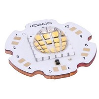
Figure 11: Standard MCPCB outline dimensions (mm).
Note for Figure 11:
1.
2.
3.
4.
5.
LedEngin,
LZP-series
Emitter heat slug mounts directly onto MCPCB copper core resulting into an extremely low
0.15C/W thermal resistance
5 Channels: 4 independent channels with strings of 6 white LED dies in series each; 1
channel for optional center pad function (not used with LZP-0xxx00 emitter)
MCPCB contains zener diodes for each channel resulting in enhanced ESD protection
6 mounting features:
o Allow for M3 or #4 screws for attaching the MCPCB to a heat sink
o Allow for alignment of LLxx-3T11 series lens holder
Product
Unless otherwise noted, the tolerance = ± 0.20 mm.
Slots in MCPCB are for M3 or #4 mounting screws.
LedEngin recommends using plastic washers to electrically insulate screws from solder pads and electrical traces.
LedEngin recommends using thermally conductive adhesives when attaching the MCPCB to a heat sink.
MCPCB thermal resistance is based on tests conducted on a copper based SuperMCPCB from Bridge Semiconductor
Inc.
Typical Emitter
4x6 MCPCB Mechanical Dimensions (mm)
0.35°C/W
RΘ
J-C
MCPCB Option – LZP-Dxxxxx
RΘ
+
+
J-B
Lookup Table
Typical MCPCB
Table 8:
12
0.15°C/W
RΘ
C-B
=
=
+10
+8
+5
-2
-4
Ch.
Typical Emitter + MCPCB
1
2
3
4
5
Pad
10
1
9
2
8
3
7
4
5
6
LZP-00WW00 (Dec. 14, 2010)
0.50°C/W
Color
RΘ
Pin Out
WW
WW
WW
WW
WW
WW
WW
WW
-
-
J-B
[1]
Function
Cathode
Cathode
Cathode
Cathode
Anode
Anode
Anode
Anode
na
na
+9
-1
+7
-3
-6
Related parts for LZP-D0NW00
Image
Part Number
Description
Manufacturer
Datasheet
Request
R

Part Number:
Description:
LED High Power (> 0.5 Watts) Warm White 90 Watts
Manufacturer:
LedEngin
Datasheet:
Part Number:
Description:
LED High Power (> 0.5 Watts) Cool White 90 Watts
Manufacturer:
LedEngin
Datasheet:

Part Number:
Description:
25 Die Cool White (5500K) LED Emitter On MCPCB
Manufacturer:
LedEngin
Datasheet:

Part Number:
Description:
LED High Power (> 0.5 Watts) Cool White 90 Watts
Manufacturer:
LedEngin
Datasheet:
Part Number:
Description:
LED High Power (> 0.5 Watts) Ultraviolet 90 Watts
Manufacturer:
LedEngin
Datasheet:
Part Number:
Description:
LED High Power (> 0.5 Watts) Ultraviolet 90 Watts
Manufacturer:
LedEngin
Datasheet:
Part Number:
Description:
LED High Power (> 0.5 Watts) Neutral Wht 90 Watts
Manufacturer:
LedEngin
Datasheet:
Part Number:
Description:
LED High Power (> 0.5 Watts) Warm White 90 Watts
Manufacturer:
LedEngin
Datasheet:
Part Number:
Description:
LED High Power (> 0.5 Watts) Ultraviolet 90 Watts
Manufacturer:
LedEngin
Datasheet:
Part Number:
Description:
LED High Power (> 0.5 Watts) Ultraviolet 90 Watts
Manufacturer:
LedEngin
Datasheet:

Part Number:
Description:
LED High Power (> 0.5 Watts) Cool White 40 Watts 12 Die 2x6 Pattern
Manufacturer:
LedEngin
Datasheet:

Part Number:
Description:
LED High Power (> 0.5 Watts) Ultraviolet 5 Watt 365 nm
Manufacturer:
LedEngin
Datasheet:
Part Number:
Description:
LED High Power (> 0.5 Watts) Neutral Wht 40 Watts 12 Die 2x6 Pattern
Manufacturer:
LedEngin
Datasheet:

Part Number:
Description:
LED High Power (> 0.5 Watts) RGBA 40 Watts
Manufacturer:
LedEngin
Datasheet:

Part Number:
Description:
LED High Power (> 0.5 Watts) Cool White 40 Watts
Manufacturer:
LedEngin
Datasheet: