LZ1-10CW03 LedEngin, LZ1-10CW03 Datasheet
LZ1-10CW03
Specifications of LZ1-10CW03
Available stocks


Related parts for LZ1-10CW03


LZ1-10CW03 Summary of contents
Page 1
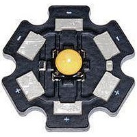
... Signaling Automotive Description The LZ1-00CW03 White LED emitter provides 3W power in an extremely small package. With a 4.4mm x 4.4mm x 3.2mm ultra-small footprint, this package provides exceptional luminous flux density times greater than competitors’ equivalent 3W products. patented thermally insulated phosphor layer provides a spatially uniform color across the radiation pattern and a consistent CCT over time and temperature ...
Page 2
... Recommended Solder Pad Layout . . . . . . . . . . . . . . . . . . . . . . . . . . . . . . . . . . . . . . . . 7 Reflow Soldering Profile . . . . . . . . . . . . . . . . . . . . . . . . . . . . . . . . . . . . . . . . . . . . . . . . Typical Relative Spectral Power Distribution . . . . . . . . . . . . . . . . . . . . . . . . . . . . . . . . . 8 Typical Relative Light Output . . . . . . . . . . . . . . . . . . . . . . . . . . . . . . . . . . . . . . . . . . . . . 9 Typical Relative Light Output over Temperature . . . . . . . . . . . . . . . . . . . . . . . . . . . . . . 9 Typical Forward Current Characteristics . . . . . . . . . . . . . . . . . . . . . . . . . . . . . . . . . . . . 10 Current Derating Curves . . . . . . . . . . . . . . . . . . . . . . . . . . . . . . . . . . . . . . . . . . . . . . . . 10 Emitter Tape & Reel Specifications . . . . . . . . . . . . . . . . . . . . . . . . . . . . . . . . . . . . . . . . 11 Company Information . . . . . . . . . . . . . . . . . . . . . . . . . . . . . . . . . . . . . . . . . . . . . . . . . . 12 LedEngin, Inc. Table of Contents LZ1-00CW03 (12/09) ...
Page 3
... I = 700mA F (lm) 145 182 228 Forward Voltage Bins Table 2: Minimum ) Forward Voltage ( 700mA @ I F (V) 2.96 3.20 3.44 3.68 3.92 3 Typical Luminous Flux (Φ [ 1000mA F (lm) 190 220 270 Maximum ) F [1] = 700mA F (V) 3.20 3.44 3.68 3.92 4.16 LZ1-00CW03 (12/09) ...
Page 4
... 0.35 0.37 Typical Bin x y CCT Code (K) 0.3551 0.3760 0.3570 0.3903 R2 5000 0.3382 0.3760 0.3376 0.3616 0.3515 0.3487 0.3551 0.3760 R3 5000 0.3376 0.3616 0.3366 0.3369 0.3498 0.3360 0.3515 0.3487 R4 5000 0.3366 0.3369 0.3361 0.3251 LZ1-00CW03 (12/09) ...
Page 5
... Figure 2: Typical representative spatial radiation pattern. LedEngin, Inc. Soak Requirements Standard Time (hrs) Conditions 168 85°C/ +5/-0 85% RH Typical Radiation Pattern Angular Displacement (Degrees) 5 Accelerated Time (hrs) Conditions n/a n/a LZ1-00CW03 (12/09) ...
Page 6
... Solder conditions per JEDEC 020D. See Reflow Soldering Profile Figure 5. 5. Autoclave Conditions per JEDEC JESD22-A102-C. 6. LedEngin recommends taking reasonable precautions towards possible ESD damages and handling the LZ1-00CW03 in an electrostatic protected area (EPA). An EPA may be adequately protected by ESD controls as outlined in ANSI/ESD S6.1. Optical Characteristics @ T ...
Page 7
... Recommended Solder Pad Layout (mm) Figure 4: Recommended solder mask opening (hatched area) for anode, cathode, and thermal pad. Note for Figure 4: 1. Unless otherwise noted, the tolerance = ± 0.20 mm. LedEngin, Inc. Figure 3: Package outline drawing. LZ1-10CW03 7 Pin Out Pad Function 1 Cathode 2 Anode ...
Page 8
... Figure 5: Reflow soldering profile for lead free soldering. Typical Relative Spectral Power Distribution 1 0.9 0.8 0.7 0.6 0.5 0.4 0.3 0.2 0.1 0 350 400 Figure 6: Relative spectral power vs. wavelength @ T LedEngin, Inc. Reflow Soldering Profile 450 500 550 600 Wavelength (nm) 8 650 700 750 800 = 25°C. C LZ1-00CW03 (12/09) ...
Page 9
... Figure 7: Typical relative light output vs. forward current @ T Typical Relative Light Output over Temperature 120 110 100 Figure 8: Typical relative light output vs. case temperature. LedEngin, Inc. 400 600 I - Forward Current (mA 25° Case Temperature (°C) 9 800 1000 100 120 LZ1-00CW03 (12/09) ...
Page 10
... Figure 10: Maximum forward current vs. ambient temperature based on T Notes for Figure 10: 1. RΘ [Junction to Case Thermal Resistance] for the LZ1-00CW03 is typically 11°C/W. J-C 2. RΘ [Junction to Ambient Thermal Resistance] = RΘ J-A LedEngin, Inc. 3.1 3.2 3.3 V ...
Page 11
... Emitter Tape and Reel Specifications (mm) Figure 11: Emitter carrier tape specifications (mm). LedEngin, Inc. Figure 12: Emitter reel specifications (mm). 11 LZ1-00CW03 (12/09) ...
Page 12
... LedEngin is committed to providing products that conserve natural resources and reduce greenhouse emissions. LedEngin reserves the right to make changes to improve performance without notice. Please contact Sales@ledengin.com LedEngin, Inc. Company Information or (408) 492-0620 for more information. 12 LZ1-00CW03 (12/09) ...