SDT042TFT Displaytech, SDT042TFT Datasheet - Page 7
SDT042TFT
Manufacturer Part Number
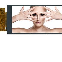
SDT042TFT
Description
TFT Displays & Accessories 4.2in TFT 432x240 RGB
Manufacturer
Displaytech
Datasheet
1.SDT042TFT-TS.pdf
(12 pages)
Specifications of SDT042TFT
Attached Touch Screen
No
Diagonal
4.2 in
Interface
Parallel
Interface Type
Parallel
Maximum Operating Temperature
+ 70 C
Minimum Operating Temperature
- 20 C
Operating Current
14.9 mA
Operating Temperature Range
- 20 C to + 70 C
Product
Displays
Supply Voltage
2.4 V to 3.3 V
Viewing Area (w X H)
49.55 mm x 97.07 mm
Pixel Density
240 x 432
Module Size (w X H X T)
54.8 mm x 113.28 mm x 3.55 mm
Backlighting
LED White
Lead Free Status / RoHS Status
Lead free / RoHS Compliant


5. Interface Description
Displaytech Ltd
Pin no
7~24
25
26
27
28
29
30
31
32
33
1
2
3
4
5
6
DB17~DB0
NWR/SCL
DOTCLK
ENABLE
NRESET
FMARK
VSYNC
HSYNC
Symbol
IOVCC
VCC
NRD
NCS
SDO
VCI
NC
RS
1.65~3.3V
2.5~3.3V
2.4~3.3V
Level
H/L
H/L
H/L
H/L
H/L
H/L
H/L
H/L
H/L
H/L
H/L
H/L
---
No connection
A supply voltage to the analog circuit. Connect to an external power supply of 2.5 ~
3.3V.
Output a frame head pulse signal.
The FMARK signal is used when writing RAM data in synchronization with frame.
Leave the pin open when not in use.
A supply voltage to the internal logic: Vcc = 2.4~3.3V
Vcc ≧ IOVcc1, IOVcc2
I/O interface supply voltage
A reset pin.
Initializes the ILI9326 with a low input. Be sure to execute a power-on reset after
supplying power.
18-bit parallel bi-directional data bus for MPU system interface mode
8-bit I/F: DB[17:10] is used.
9-bit I/F: DB[17:9] is used.
16-bit I/F: DB[17:10] and DB[8:1] is used.
18-bit I/F: DB[17:0] is used.
18-bit parallel bi-directional data bus for RGB interface operation
6-bit RGB I/F: DB[17:12] are used.
16-bit RGB I/F: DB[17:13] and DB[11:1] are used.
18-bit RGB I/F: DB[17:0] are used
A read strobe signal and enables an operation to read out data when the signal is low.
Fix to IOVcc1 level when not in use.
A write strobe signal and enables an operation to write data when the signal is low.
Fix to either IOVcc1 level when not in use.
SPI Mode:
Synchronizing clock signal in SPI mode.
A register select signal.
Low: select an index or status register
High: select a control register
Fix to GND level when not in use.
A chip select signal.
Low: the ILI9326 is selected and accessible
High: the ILI9326 is not selected and not accessible
Fix to the IOVcc1 level when not in use.
Frame synchronizing signal for RGB interface operation.
VSPL = “0”: Active low.
VSPL = “1”: Active high.
Fix to GND level when not in use.
Line synchronizing signal for RGB interface operation.
HSPL = “0”: Active low.
HSPL = “1”: Active high.
Fix to GND level when not in use.
Dot clock signal for RGB interface operation.
DPL = “0”: Input data on the rising edge of DOTCLK
DPL = “1”: Input data on the falling edge of DOTCLK
Fix to GND level when not in use.
Data ENEABLE signal for RGB interface operation.
Low: Select (access enabled)
High: Not select (access inhibited)
The EPL bit inverts the polarity of the ENABLE signal.
SPI interface output pin.
The data is outputted on the falling edge of the SCL signal.
Let SDO as floating when not used
LCD MODULE
6
SDT042TFT / SDT042TFT-TS
Description
Version: 1.0
Related parts for SDT042TFT
Image
Part Number
Description
Manufacturer
Datasheet
Request
R


Part Number:
Description:
TFT Displays & Accessories 3.3in TFT 320x480 RGB w/touch
Manufacturer:
Displaytech
Datasheet:

Part Number:
Description:
TFT Displays & Accessories 5.7 TFT w/Touch Screen
Manufacturer:
Displaytech
Datasheet:

Part Number:
Description:
TFT Displays & Accessories 4.2in TFT 432x240 RGB w/touch
Manufacturer:
Displaytech
Datasheet:

Part Number:
Description:
TFT Displays & Accessories 7.0 TFT w/Touch Screen
Manufacturer:
Displaytech
Datasheet:
Part Number:
Description:
TFT Displays & Accessories 3.3in TFT 320x480 RGB
Manufacturer:
Displaytech
Datasheet:

Part Number:
Description:
TFT Displays & Accessories 2.2in TFT
Manufacturer:
Displaytech
Datasheet:
Part Number:
Description:
TFT Displays & Accessories 5.7 TFT
Manufacturer:
Displaytech
Datasheet: