SDT033TFT-TS Displaytech, SDT033TFT-TS Datasheet - Page 7
SDT033TFT-TS
Manufacturer Part Number
SDT033TFT-TS
Description
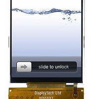
TFT Displays & Accessories 3.3in TFT 320x480 RGB w/touch
Manufacturer
Displaytech
Datasheet
1.SDT033TFT-TS.pdf
(12 pages)
Specifications of SDT033TFT-TS
Attached Touch Screen
Yes
Diagonal
3.3 in
Interface
Parallel
Interface Type
Parallel
Maximum Operating Temperature
+ 60 C
Minimum Operating Temperature
- 10 C
Operating Current
39.66 mA
Operating Temperature Range
- 10 C to + 60 C
Product
Displays
Supply Voltage
2.5 V to 3.3 V
Touch Panel
Touch Panel
Viewing Area (w X H)
51.36 mm x 74.74 mm
Pixel Density
320 x 480
Module Size (w X H X T)
55.7 mm x 84 mm x 2.8 mm
Backlighting
LED White
Lead Free Status / RoHS Status
Lead free / RoHS Compliant
Available stocks
Company
Part Number
Manufacturer
Quantity
Price
Company:

Part Number:
SDT033TFT-TS
Manufacturer:
Displaytech
Quantity:
135
Company:
Part Number:
SDT033TFT-TS
Manufacturer:
SAMSUNG
Quantity:
1 000


5. Interface Description
Displaytech Ltd
20 ~ 37
Pin no
5 ~ 6
10
11
12
13
14
15
16
17
18
19
38
1
2
3
4
7
8
9
RWB_RDB
DOTCLK
ENABLE
D17 ~ D0
E_WRB
VSYNC
HSYNC
Symbol
IOVCI
LEDK
LEDA
RSTB
GND
GND
SDO
SPI3
VCI
SCL
SDI
CS
RS
1.65~3.3V
2.5~3.3V
Level
H/L
H/L
H/L
H/L
H/L
H/L
H/L
H/L
H/L
H/L
H/L
H/L
H/L
H/L
0V
0V
---
---
Ground
LED Backlight cathode
LED Backlight anode
Ground
Analog power supply
I/O power supply for external interface.
Chip selection
In M68 mode, this is used to select operation, read or write (RWB).
In I80 mode, this serves as a read strobe signal (RDB).
The signal for register index or register command select.
Low: Register index or internal status (in read operation)
High: Register command.
In M68 mode, this serves as a write/read enable strobe (E).
In I80 mode, this serves as a write strobe signal (WRB).
Frame synchronizing signal
Horizontal Line synchronizing signal
Dot clock signal
A data ENABLE signal in the RGB I/F mode
Serial data transfer output in the serial data transfer interface mode
Serial data transfer input/output in the serial data transfer interface mode
In SPI mode, this serves as a synchronous clock (SCL)
Reset pin. Setting this pin to low initializes the LSI. Must be reset after power is
supplied
Data bus for SYSTEM I/F
Data bus for RGB I/F
Connected unused pins to the IOVCI or VSS level
Mode selection pin for Serial Peripheral Interface.
If SPI3 = 0, 4-wire SPI mode
If SPI3 = 1, 3-wire SPI mode. That is, SDI is bidirectional pin.
6-bit interface, 3-transfer
16-bit interface, 1-transfer
18-bit interface, 1-transfer
IM[3:0]
4’b0000
4’b0001
4’b0010
4’b0011
4’b010x
4’b011x
4’b1000
4’b1001
4’b1010
4’b1011
4’b1100
4’b1110
4’b1101
4’b1111
LCD MODULE
Interface Mode
Interface Mode
M68,16-bit bus interface
M68, 8-bit bus interface
I80, 16-bit bus interface
I80, 8-bit bus interface
Serial peripheral interface
Serial peripheral interface
M68, 18-bit bus interface
M68, 9-bit bus interface
I80, 18-bit bus interface
I80, 9-bit bus interface
Reserved
Reserved
Reserved
Reserved
Description
6
SDT033TFT / SDT033TFT-TS Version: 2.1
Description
DB[8:1]
DB[17:10]
DB[8:1]
DB[17:10]
-
-
DB[8:1]
DB[17:10]
DB[8:1]
DB[17:10]
-
-
-
-
DB[17:12]
DB[17:13],DB[11:1]
DB[17:0]
Index
Description
Description
DB[17:10],DB[8:1]
DB[17:10]
DB[17:10],DB[8:1]
DB[17:10]
-
-
DB[17:0]
DB[17:9]
DB[17:0]
DB[17:9]
-
-
-
-
Data
Related parts for SDT033TFT-TS
Image
Part Number
Description
Manufacturer
Datasheet
Request
R


Part Number:
Description:
TFT Displays & Accessories 5.7 TFT w/Touch Screen
Manufacturer:
Displaytech
Datasheet:

Part Number:
Description:
TFT Displays & Accessories 4.2in TFT 432x240 RGB w/touch
Manufacturer:
Displaytech
Datasheet:

Part Number:
Description:
TFT Displays & Accessories 7.0 TFT w/Touch Screen
Manufacturer:
Displaytech
Datasheet:

Part Number:
Description:
TFT Displays & Accessories 3.3in TFT 320x480 RGB
Manufacturer:
Displaytech
Datasheet:

Part Number:
Description:
TFT Displays & Accessories 2.2in TFT
Manufacturer:
Displaytech
Datasheet:
Part Number:
Description:
TFT Displays & Accessories 5.7 TFT
Manufacturer:
Displaytech
Datasheet:

Part Number:
Description:
TFT Displays & Accessories 2.4in TFT
Manufacturer:
Displaytech
Datasheet: