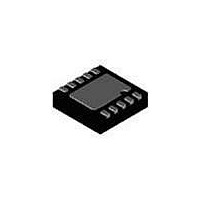
SP7685ER-L Exar Corporation, SP7685ER-L Datasheet - Page 5

SP7685ER-L
Manufacturer Part Number
SP7685ER-L
Description
LED Drivers 1.2A Bck/Bst Charge Pump LED Driver
Manufacturer
Exar Corporation
Series
-r
Datasheet
1.SP7685ER-L.pdf
(12 pages)
Specifications of SP7685ER-L
Low Level Output Current
0.4 A
High Level Output Current
2 A
Operating Supply Voltage
2.7 V to 5.5 V
Maximum Operating Temperature
+ 85 C
Mounting Style
SMD/SMT
Package / Case
DFN-10
Minimum Operating Temperature
- 40 C
Constant Current
-
Constant Voltage
-
Topology
PWM, Step-Down (Buck), Step-Up (Boost), Switched Capacitor (Charge Pump)
Number Of Outputs
1
Internal Driver
Yes
Type - Primary
Backlight, Flash/Torch
Type - Secondary
High Brightness LED (HBLED), White LED
Frequency
2.4MHz
Voltage - Supply
2.7 V ~ 5.5 V
Voltage - Output
-
Mounting Type
Surface Mount
Operating Temperature
-40°C ~ 85°C
Lead Free Status / RoHS Status
Lead free / RoHS Compliant
Available stocks
Company
Part Number
Manufacturer
Quantity
Price
Company:
Part Number:
SP7685ER-L/TR
Manufacturer:
EXAR
Quantity:
3 500
In the Torch mode, (Flash = GND) the Flash
pin is set to logic low and the SP7685 FB pin
regulates to 50mV output:
V
When in Flash mode, (Flash = V
regulation voltage is set by the resistor R
connected between the R
and the equation:
V
Where 14μA is an internal regulated
current and 5 is an internal factor used to
scale the V
Typical values of R
35KΩ for a range of V
100mV in Flash mode.
The output current is then set in either Flash
or Torch mode by the equation:
I
Due to the high currents typically available
in Flash mode, it is necessary to protect the
white LED from damage if left on too long.
The SP7685 has a timeout in Flash mode of
approximately 2.6 seconds after which it will
shut down operation.
begin again in Flash mode until the Enable
pin or Flash pin have been set Low and then
High again.
When the temperature of the SP7685 rises
above 145
OUT
Date: 6/20/06 Rev T
FB
FB
OVERTEMPERATURE PROTECTION
= 50mV (Torch Mode)
= R
= V
SET
FB
FLASH TIMEOUT PROTECTION
/ R
˚
* 14μA / 5 (Flash Mode)
C, the overtemperature protec-
SET
SENSE
voltage to the V
SET
FB
are 140KΩ to
= 400mV to
Operation will not
SET
SP7685, 1.2A Buck/BoostCharge Pump LED Driver
pin and S
FB
IN
voltage.
), the FB
GND
SET
5
tion circuitry turns off the output switches
to prevent damage to the device. If the
temperature drops back down below 135
degrees Celsius, the part automatically
recovers and executes a soft start cycle.
The over current protection circuitry moni-
tors the average current out of the V
pin. If the average output current exceeds
approximately 1.6 Amps, then the
overcurrent protection circuitry shuts off
the output switches to protect the chip.
BRIGHTNESS CONTROL USING PWM
Dimming control can be achieved by ap-
plying a PWM control signal to the EN pin.
The brightness of the white LEDs is con-
trolled by increasing and decreasing the
duty cycle of the PWM signal. While the
operating frequency range of the PWM
control is from 60Hz to 700Hz, the recom-
mended maximum brightness frequency
range of the PWM signal is from 60Hz to
200Hz. A repetition rate of at least 60Hz is
required to prevent flicker.
The SP7685 has over voltage protec-
tion. If the output voltage rises above
the 5.5V threshold, the over voltage
protection shuts off all of the output
switches to prevent the output voltage
from rising further. When the output
decreases below 5.5V, the device re-
sumes normal operation.
OVERVOLTAGE PROTECTION
OVERCURRENT PROTECTION
THEORY OF OPERATION
© 2006 Sipex Corporation
OUT


